Polishing device for galvanized iron alloy door machining

A ferroalloy and mounting plate technology, applied in grinding drive devices, metal processing equipment, grinders, etc., can solve the problems of low efficiency of galvanized ferroalloy doors and inconvenient door turning, achieve fast clamping speed, reduce vibration and noise , Improve the effect of grinding efficiency

Inactive Publication Date: 2020-03-24
湖南瑞泰欣金属有限公司
View PDF5 Cites 4 Cited by
  • Summary
  • Abstract
  • Description
  • Claims
  • Application Information

AI Technical Summary

Problems solved by technology

[0003] The commonly used material of the door body of the anti-theft door is galvanized iron alloy. During the production process, the door body needs to be polished. Manual grinding of the galvanized iron alloy door is inefficient and inconvenient for the door body to turn over.

Method used


Image

  • Polishing device for galvanized iron alloy door machining
  • Polishing device for galvanized iron alloy door machining
  • Polishing device for galvanized iron alloy door machining

Examples


Embodiment 1

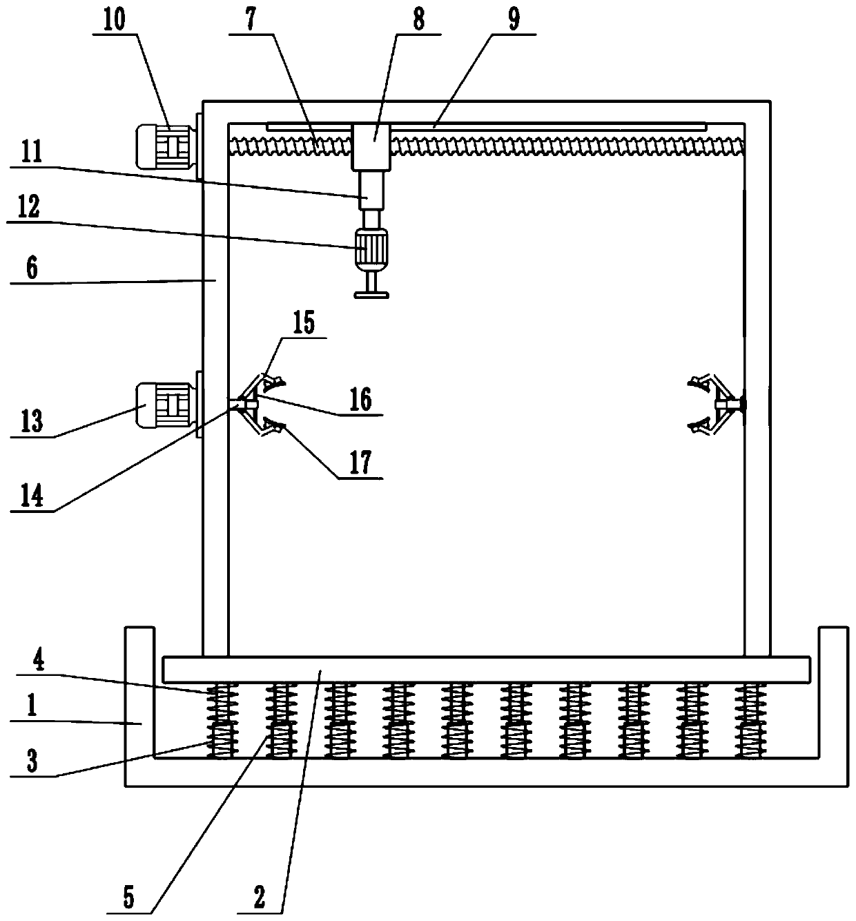
[0020] see Figure 1-3 , in an embodiment of the present invention, a grinding device for processing galvanized ferroalloy doors includes a base 1, a mounting plate 2, a fixing frame 6, an electric telescopic rod 11 and a grinding motor 12, and a mounting Plate 2, the upper surface of mounting plate 2 is fixedly connected with fixed frame 6, and the inside of fixed frame 6 is provided with screw mandrel 7, and the left and right ends of screw mandrel 7 are respectively connected with the side wall of fixed frame 6 in rotation, and the outside of fixed frame 6 The wall is fixedly connected with a translation motor 10, the translation motor 10 is a forward and reverse motor, the shaft extension end of the translation motor 10 is connected with the end of the screw rod 7, and the forward and reverse rotation of the translation motor 10 is controlled, which can drive the forward and reverse rotation of the screw mandrel 7 , the middle part of the screw rod 7 is provided with a sli...

Embodiment 2

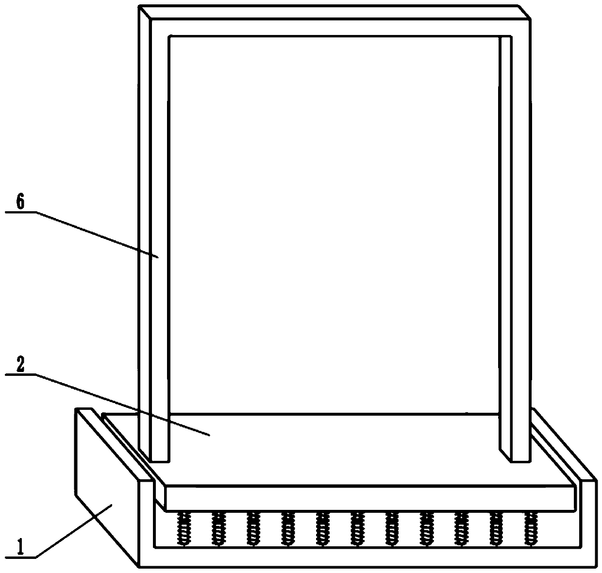
[0022] On the basis of Embodiment 1, a sleeve 3 is fixedly connected to the upper surface of the base 1, and a guide column 4 is installed inside the sleeve 3, and the guide column 4 is slidingly connected with the sleeve 3, and the guide column 4 can slide along the sleeve 3 slide up and down, the top of the guide column 4 is fixedly connected with the mounting plate 2, the sleeve 3 is covered with a spring 5, the lower end of the spring 5 is fixedly connected with the upper surface of the base 1, and the upper end of the spring 5 is connected with the lower surface of the mounting plate 2. The surface is fixedly connected, and the spring 5 can be used for shock absorption to reduce the vibration of the mounting plate 2, thereby reducing the vibration and noise of the device during operation.

Embodiment 1、 Embodiment 2

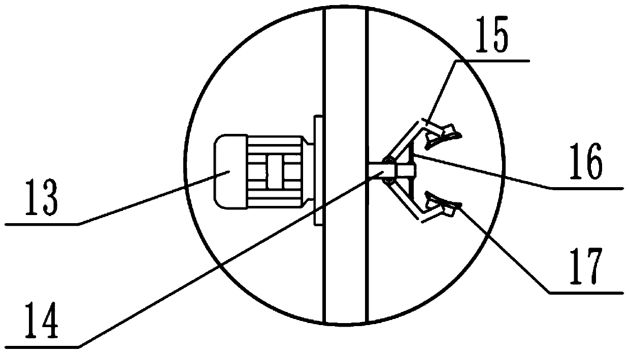
[0023] Combined with Embodiment 1 and Embodiment 2, the working principle of the present invention is: place the galvanized iron alloy door to be polished between the two claws 15, control the extension of the hydraulic telescopic cylinder 14, and drive the two claws 15 to close together. Utilize the clamping plate 17 to clamp the galvanized iron alloy door to be polished, so as to facilitate the grinding operation, start the grinding motor 12, drive the grinding head to rotate, and control the extension of the electric telescopic rod 11, so that the grinding head and the surface of the door body are connected. The grinding head grinds the surface of the galvanized iron alloy door. When the door body needs to be turned over, the rotating motor 13 is controlled to run, and the clamping mechanism is driven to rotate, thereby driving the door body to rotate, which is convenient for adjusting the grinding position. The vibration of the mounting plate 2 is reduced, thereby reducing ...


PUM


Abstract

The invention relates to the field of grinding equipment, and more particularly, relates to a polishing device for galvanized iron alloy door machining. The polishing device for galvanized iron alloydoor machining comprises a base, a mounting plate, a fixing frame, an electric telescopic rod and a grinding motor, wherein the mounting plate is arranged above the base; the upper surface of the mounting plate is fixedly connected with the fixing frame; a screw rod is arranged in the fixing frame; the left and right ends of the screw rod are rotationally connected with the side wall of the fixingframe; the outer side wall of the fixing frame is fixedly connected with a translation motor; the shaft extension end of the translation motor is connected with the end part of the screw rod; the middle of the screw rod is sleeved with a sliding block; an electric telescopic rod is mounted on the lower surface of the sliding block; a polishing motor is installed at the lower end of the electric telescopic rod; a rotating motor is fixedly connected to the side wall of the fixing frame; clamping mechanisms are symmetrically installed on the inner walls of the left side and the right side of thefixing frame; a galvanized iron alloy door to be polished is placed between two clamping jaws; and the galvanized iron alloy door to be polished is clamped through the clamping mechanisms. The clamping speed is high, and assembling and disassembling are convenient.

Description

technical field [0001] The invention relates to the field of grinding equipment, in particular to a grinding device for processing galvanized ferroalloy doors. Background technique [0002] The full name of anti-theft door is "anti-theft safety door". It has both anti-theft and safety performance. According to the "General Technical Conditions for Anti-theft Safety Doors", a qualified anti-theft door cannot be pried open by ordinary hand tools such as chisels, screwdrivers, crowbars, and portable electric tools such as electric hand drills within 15 minutes or a 615 square millimeter hole can be opened on the door leaf. opening, or a 38 mm2 opening within a semicircle of 150 mm2 at the locking point. And the lock used on the security door must be the special lock for the security door with anti-drilling function after passing the test by the Testing Center of the Ministry of Public Security. [0003] The commonly used material of the door body of the anti-theft door is ga...

Claims


Application Information

Patent Timeline
IPC IPC(8): B24B19/00B24B41/06B24B47/12B24B41/00F16F15/04
CPCB24B19/00B24B41/007B24B41/06B24B47/12F16F15/04
Inventor 文红军聂美娇
Owner 湖南瑞泰欣金属有限公司
Why Eureka
Try Eureka