
Variable-frequency parking air conditioner

A frequency conversion and parking technology, which is applied to vehicle components, air handling equipment, heating/cooling equipment, etc., can solve the problem that the anti-vibration performance of the air conditioner cannot meet the vibration road conditions of the vehicle, the running time of the parking air conditioner is shortened, and the user's needs cannot be met, etc. problems, to achieve the effect of meeting vehicle vibration requirements, improving service life and high reliability

Pending Publication Date: 2020-03-24
GREE ELECTRIC APPLIANCES INC
View PDF0 Cites 2 Cited by
  • Summary
  • Abstract
  • Description
  • Claims
  • Application Information

AI Technical Summary

Problems solved by technology

[0002] It usually takes a long time for large trucks to stop for loading and unloading. In hot weather, the driver needs to turn on the air conditioner to maintain a comfortable cabin temperature. However, the original car air conditioner needs to be on when the vehicle is parked. Accelerated wear and tear of the engine and shortened service life, so many large trucks are equipped with parking air conditioners, but the current general parking air conditioners are of a split structure. On the side wall of the truck, the anti-vibration performance of the air conditioner is often unable to meet the vibration road conditions of the vehicle
At the same time, the fixed-frequency air conditioner used in the general parking air conditioner and the fixed-frequency compressor used in the fixed-frequency air conditioner have the characteristics of high energy consumption and low energy efficiency, which shortens the running time of the parking air conditioner originally powered by the car battery and cannot satisfy users. need

Method used


Image

  • Variable-frequency parking air conditioner
  • Variable-frequency parking air conditioner
  • Variable-frequency parking air conditioner

Examples


Embodiment Construction

[0028] The present invention is further described in conjunction with the following examples.

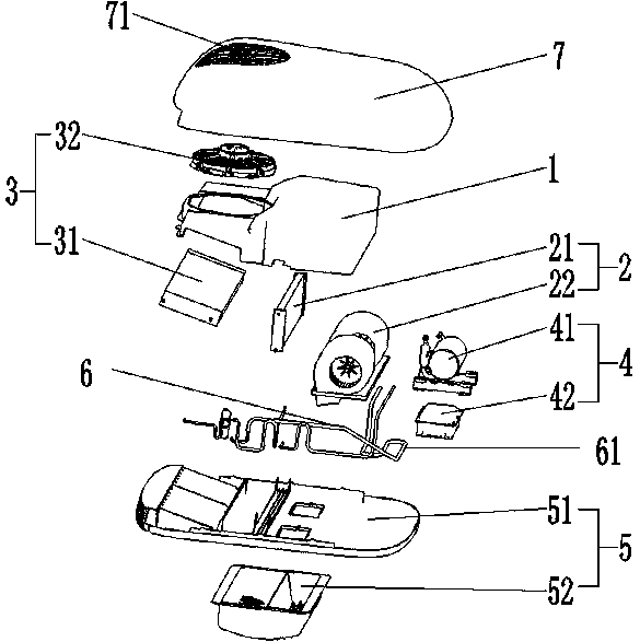
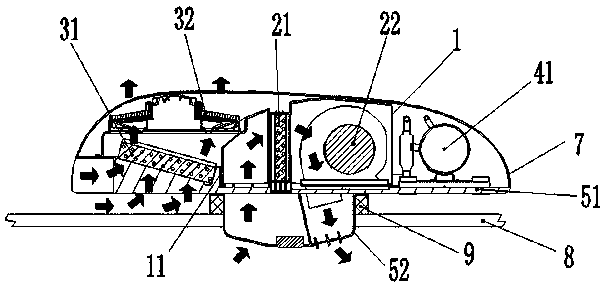
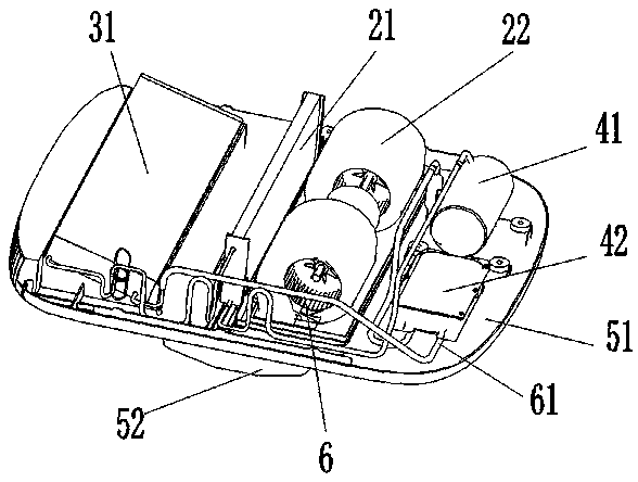
[0029] like Figure 1-7 As shown, the embodiment of the present invention is an inverter parking air conditioner, which includes a fan mounting part 1, an inner heat exchange assembly 2, an outer heat exchange assembly 3, a driving device 4 and a chassis assembly 5, and the driving device 4 is fixed on the chassis assembly 5 Above, the fan mounting part 1 is located on one side of the driving device 4 and is fixedly connected with the chassis assembly 5. The fan mounting part 1 is provided with a partition 11 for dividing the fan mounting part 1 into two storage spaces. The partition 11 The right side of the partition is the first closed space 13, and the left side of the partition is the second closed space 14. The inner heat exchange assembly 2 and the outer heat exchange assembly 3 are respectively located on both sides of the partition 11 and there is no air flow between them. ...


PUM


Abstract

The invention provides a variable-frequency parking air conditioner. The heat exchanger comprises a fan installation part, an inner side heat exchange assembly, an outer side heat exchange assembly, adriving device and a chassis assembly, the driving device is fixed on the chassis assembly; the fan installation part is positioned on one side of the driving device and is fixedly connected with thechassis assembly; a partition plate used for dividing the draught fan installation part into two containing spaces is arranged in the draught fan installation part. The inner side heat exchange assembly and the outer side heat exchange assembly are located on the two sides of the partition plate correspondingly and do not exchange airflow. The driving device communicates with the inner side heatexchange assembly and the outer side heat exchange assembly through pipeline connecting parts. The variable-frequency parking air conditioner has the advantages that extra pipeline connection during installation can be avoided, reliability is high, vehicle-mounted vibration requirements can be met, low energy consumption, high energy efficiency and high energy-saving effect are achieved, and running time of the parking air conditioner is prolonged.

Description

technical field [0001] The invention relates to the technical field of parking air conditioners, in particular to a frequency conversion type parking air conditioner. Background technique [0002] It usually takes a long time for large trucks to park for loading and unloading. In hot weather, the driver needs to turn on the air conditioner to maintain a comfortable cabin temperature. However, when parking, the vehicle engine needs to be kept on when using the original car air conditioner. Accelerated wear and tear of the engine and shortened service life, so many large trucks are equipped with parking air conditioners, but the current general parking air conditioners are of a split structure. On the side wall of the truck, the anti-vibration performance of such an air conditioner is often unable to meet the vibration road conditions of the vehicle. At the same time, the fixed-frequency air conditioner used in the general parking air conditioner and the fixed-frequency compr...

Claims


Application Information

Patent Timeline
Patent Type & Authority Applications(China)
IPC IPC(8): B60H1/00B60H1/32
CPCB60H1/00321B60H1/00357B60H1/00507B60H1/3204Y02T10/88
Inventor 黄传曦
Owner GREE ELECTRIC APPLIANCES INC
Learn More