Winding equipment for yarn of roving frame

A roving frame and yarn technology, which is applied in the field of yarn winding, can solve the problems that the yarn moving direction cannot be changed, the yarn is unevenly wound, and the workload of the staff is large, so as to avoid the conveyor belt from breaking and not easy to jam yarn effect

Inactive Publication Date: 2020-03-24
巢湖市春维纺织有限公司
View PDF5 Cites 1 Cited by
  • Summary
  • Abstract
  • Description
  • Claims
  • Application Information

AI Technical Summary

Problems solved by technology

[0005] 1) The yarn can be evenly wound on the winding drum through the hydraulic push rod and the wire roller, and the moving direction of the yarn can be changed, so that the winding drum can keep the straight line for winding the yarn, which solves the problem of existing roving The yarn is unevenly wound on the winding drum of the machine yarn winding equipment and brings a huge workload to the staff. The moving direction of the yarn cannot be changed, and the technical problem of winding the yarn in a straight line cannot be maintained;
[0006] 2) By setting the vertical bevel gear and the horizontal bevel gear, the transformation of the horizontal rotation axial force of the motor can be effectively realized, and the breakage of the conveyor belt due to the use of the conveyor belt linkage can be effectively avoided, which solves the problem that the existing winding equipment for roving frame yarn uses the conveyor belt The change of force caused the technical problem that the winding machine box as a whole stopped operating and could not guarantee the normal, durable and efficient operation of the winding machine box as a whole

Method used


Image

  • Winding equipment for yarn of roving frame
  • Winding equipment for yarn of roving frame
  • Winding equipment for yarn of roving frame

Examples


Embodiment Construction

[0031] The technical solutions in the embodiments of the present invention will be clearly and completely described below in conjunction with the embodiments of the present invention. Obviously, the described embodiments are only a part of the embodiments of the present invention, rather than all the embodiments. Based on the embodiments of the present invention, all other embodiments obtained by those of ordinary skill in the art without creative work shall fall within the protection scope of the present invention.

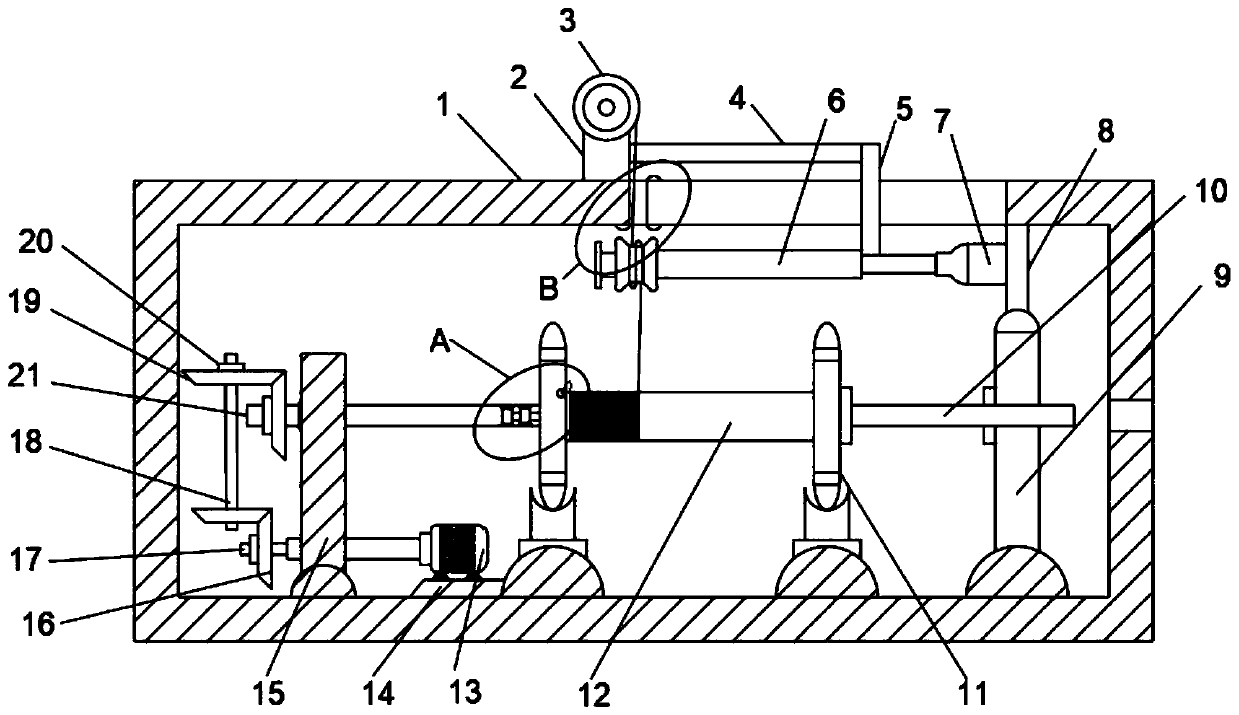
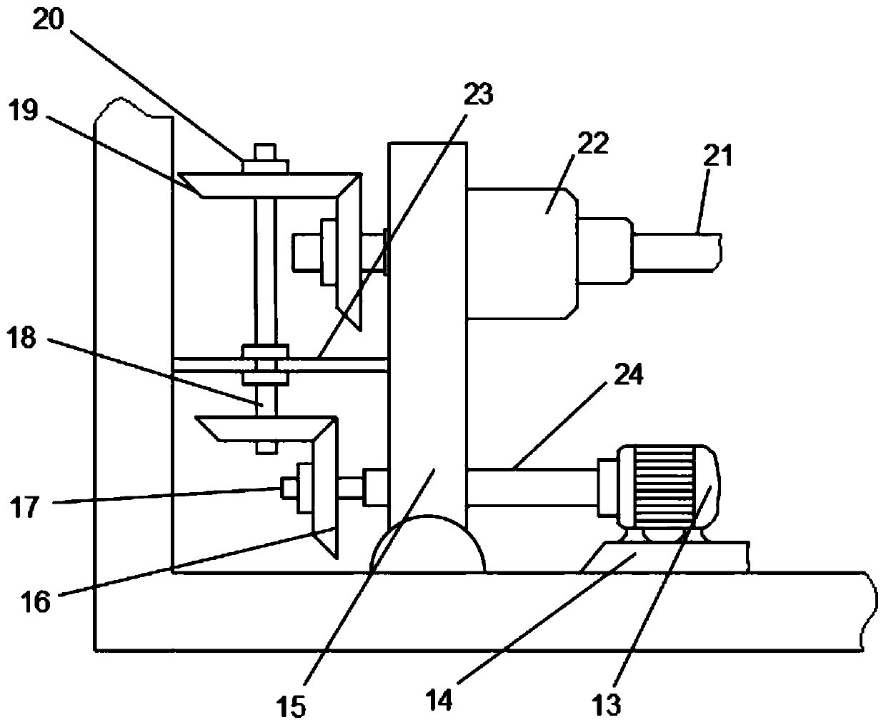
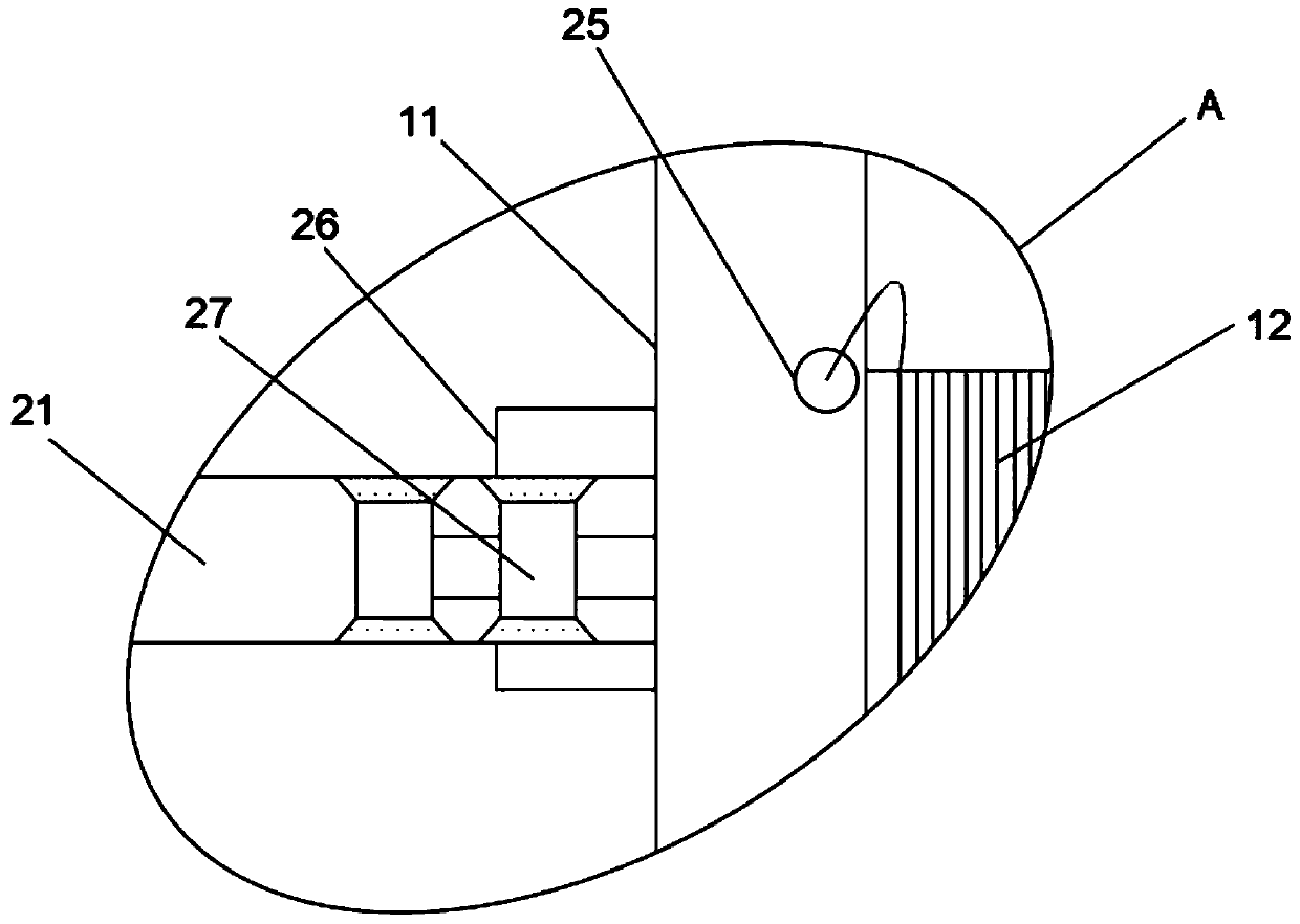
[0032] Such as Figure 1-5 As shown, a yarn winding device for a roving frame includes a winding box body 1, the upper end surface of the winding box body 1 is provided with a top support 2 and the upper end surface of the top support 2 is provided with a wire roller 3, The right end surface of the top pillar 2 is provided with a first connecting rod 4, the right end surface of the first connecting rod 4 is provided with an L-shaped connecting rod 5, and the left en...


PUM


Abstract

The invention discloses winding equipment for a yarn of a roving frame. The winding equipment comprises a winding machine box. A top supporting column is arranged on the surface of the upper end of the winding machine box body; a wire guiding roller is arranged on the surface of the upper end of the top supporting column; a first connecting rod is arranged on the surface of the right end of the top supporting column; an L-shaped connecting rod is arranged on the surface of the right end of the first connecting rod; and a second connecting rod is arranged on the surface of the left end of the L-shaped connecting rod. According to the winding equipment, the yarn can be uniformly wound on the winding drum, the moving direction of the yarn can be changed, and the winding drum can wind the yarnin a straight line, so that yarn jamming is not prone to occurring, use of a user is facilitated, conversion of the horizontal rotating axial force of a motor can be effectively achieved, the servicelife is longer, normal and lasting efficient operation of the whole winding machine box can be guaranteed, the phenomenon that the yarn is disengaged in the winding process, and consequently invalidwinding work is caused is avoided, and convenience is brought to work of workers.

Description

Technical field [0001] The invention belongs to the technical field of yarn winding, in particular to a yarn winding device for a roving frame. Background technique [0002] The purpose of winding is to facilitate the storage, transportation and feeding of products to the next process for processing. Sometimes in order to change the package capacity, remove defects and improve quality, it is necessary to rewind or rewind. Common simple winding methods, such as various fiber rolls, warp beams, weaving beams, and cloth shafts, only use simple rotary motions to wind finished or semi-finished products into the required cylindrical package. In the spinning process, the single-end yarn winding in addition to the revolving movement of the winding, there is also the reciprocating movement of the winding point relative to the package, so that the yarn continuously reciprocates or rises and falls along the axis of the package. The combination of this movement causes the yarn to be wound ...

Claims


Application Information

Patent Timeline
Patent Type & Authority Applications(China)
IPC IPC(8): B65H54/28B65H54/74
CPCB65H54/2818B65H54/74B65H2701/31
Inventor 朱清林黄涛陆云山
Owner 巢湖市春维纺织有限公司
Why Eureka
Try Eureka