
A construction method of hangar concrete surface structure

A concrete surface and construction method technology, applied in the direction of floors, building structures, buildings, etc., can solve the difficulty of ensuring the flatness and straightness of steel corner protection, the difficulty of installing and reinforcing steel corner protection, and the complicated construction process of steel corner protection and other problems, to achieve the effect of solving the difficulties of installation and reinforcement, saving layout and easy operation

Active Publication Date: 2021-04-02
BEIJING NO 3 CONSTR ENG
View PDF5 Cites 0 Cited by
  • Summary
  • Abstract
  • Description
  • Claims
  • Application Information

AI Technical Summary

Problems solved by technology

[0003] The purpose of the present invention is to provide a construction method for the hangar concrete surface structure, to solve the difficulty of installing and reinforcing the traditional steel corner protection, waste of steel bars, difficulty in ensuring the flatness and straightness of the steel corner protection, and the construction process of the steel corner protection Technical problems of complex and slow construction progress

Method used


Image

  • A construction method of hangar concrete surface structure
  • A construction method of hangar concrete surface structure
  • A construction method of hangar concrete surface structure

Examples


Embodiment Construction

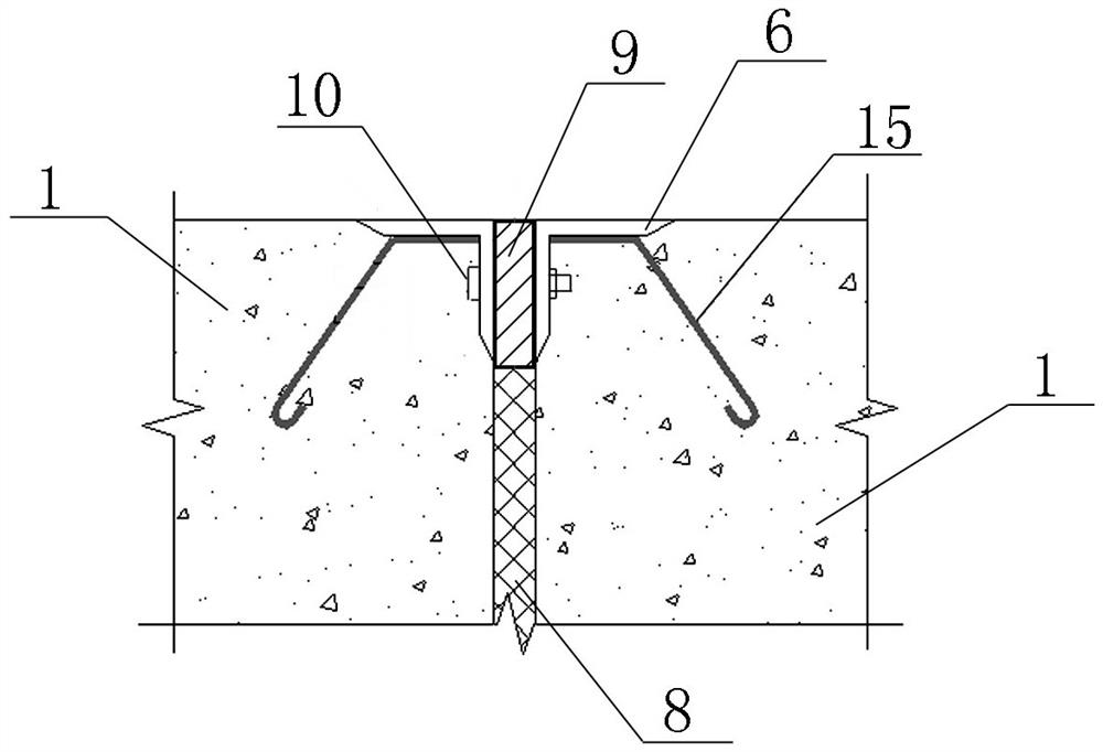
[0045] This embodiment is designed for a 400mm thick concrete ground steel formwork and angle steel angle protection system in a certain project. The longitudinal side form is used to connect the steel angle protection 6 with bolts 10 to solve the technical problem of difficult installation and reinforcement of the steel angle protection 6, and The flatness and straightness of the steel corner protector 6 are guaranteed, and the construction process of the steel corner protector 6 is simplified at the same time, and the construction progress is accelerated.

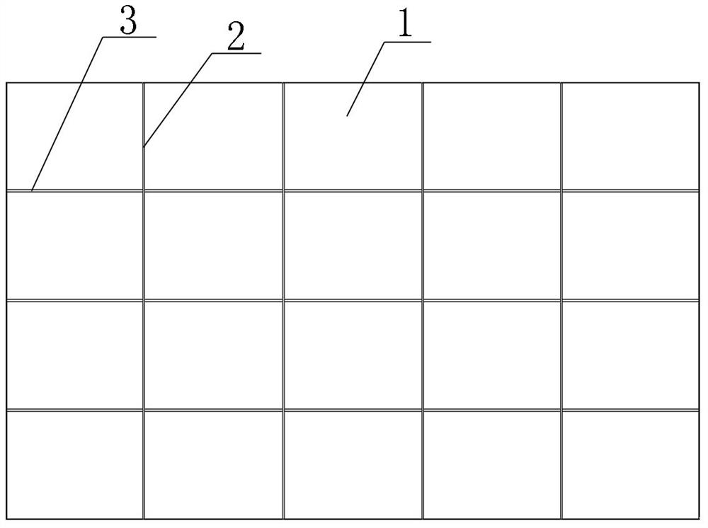
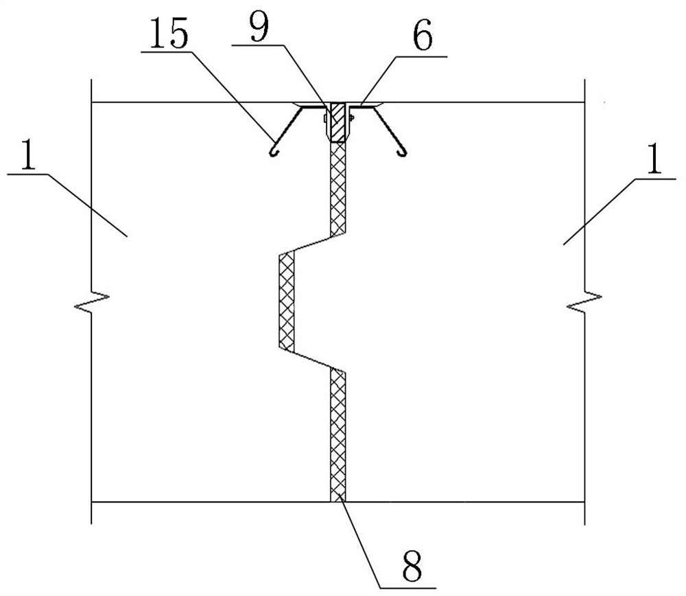
[0046] like Figure 1-4As shown, the hangar concrete surface structure includes a concrete unit block 1; the concrete unit block 1 is formed by casting in-situ, and the concrete unit block 1 has one group, which is arranged in a matrix; the horizontally adjacent concrete unit blocks 1 are separated by longitudinal partitions 2; vertically adjacent concrete unit blocks 1 are separated by transverse partitions 3; the side o...


PUM

PropertyMeasurementUnit
lengthaaaaaaaaaa
widthaaaaaaaaaa
thicknessaaaaaaaaaa

Abstract

The invention relates to a hangar concrete surface layer structure and a construction method thereof. The hangar concrete surface layer structure comprises concrete unit blocks, wherein a group of concrete unit blocks are provided and are arranged in a matrix shape, the longitudinally adjacent concrete unit blocks are separated by transverse separation seams, first grooves are formed in the side faces of the concrete unit blocks on one sides of longitudinal separation seams, first protrusions are arranged on the side faces of the concrete unit blocks on the other sides of the longitudinal separation seams, the first protrusions are inserted into the first grooves, the edges of the concrete unit blocks are provided with steel angle beads correspondingly, the cross sections of the steel angle beads are inverted-L shaped, connecting holes are formed in the vertical edges of the steel angle beads, the steel angle beads on the two sides of the longitudinal separation seams are connected through bolts, the longitudinal separation seams are filled with foam boards, and the positions, located between the corresponding steel angle beads, at the upper portion of each longitudinal separationseam is filled with a sealing strip. According to the hangar concrete surface layer structure and the construction method thereof, the technical problems that the traditional steel angle bead installation and reinforcement are difficult, steel bars are wasted, the flatness and the straightness of the steel angle beads are difficult to guarantee, the construction process of the steel angle beads iscomplex, and the construction progress is relatively slow are solved.

Description

technical field [0001] The invention belongs to the field of building engineering construction, in particular to a construction method for a hangar concrete surface structure. Background technique [0002] The floor of the hangar hall of a certain project is a 400mm thick cast-in-place reinforced concrete floor, with a total area of ​​14655.9㎡ and a plane size of 147×99.7m. During the pouring process of the floor concrete surface, it is necessary to set up longitudinal joints, and set steel corner guards at the top corners of the longitudinal joints. The traditional angle steel corner is fixed by welding the anchor bar and the measure steel bar. This setting method has the difficulties of installing and reinforcing the angle steel, wasting steel bars, and it is difficult to guarantee the flatness and straightness of the angle steel corner. The construction process of the angle steel corner is complicated and the construction progress The downside of being slower. Contents...

Claims


Application Information

Patent Timeline
Patent Type & Authority Patents(China)
IPC IPC(8): E04F15/12E04F15/14
CPCE04F15/12E04F15/142
Inventor 齐翰郏存金王茂同王南胡高永孟佳纬
Owner BEIJING NO 3 CONSTR ENG
Learn More