Pump body assembly, heat exchange equipment, fluid machine and operation method of fluid machine

A technology of fluid machinery and components, applied in the direction of liquid variable displacement machinery, pump components, mechanical equipment, etc., can solve the problems of large exhaust resistance, reduced effective exhaust area, and increased exhaust pressure, so as to improve overcompression , the effect of increasing the exhaust area

Pending Publication Date: 2020-03-24
GREE ELECTRIC APPLIANCES INC
View PDF9 Cites 3 Cited by
  • Summary
  • Abstract
  • Description
  • Claims
  • Application Information

AI Technical Summary

Problems solved by technology

The exhaust channel area is the product of the distance between the extrusion end surface and the radial direction of the cylinder and the cross-sectional height. During the exhaust process, the high-pressure gas outside the exhaust port first flows through the space between the piston extrusion end surface and the cylinder, and then However, as the distance between the piston extrusion end surface and the radial direction of the cylinder decreases, the exhaust area is much smaller than the exhaust port area. As the distance decreases, the effective exhaust area also continues. Reduced, resulting in large exhaust resistance, increased exhaust pressure, higher than the design exhaust pressure, the entire compression chamber appears overcompression, affecting the energy efficiency of the compressor
[0003] In view of this, the Chinese patent CN107387410A discloses a technical solution for pressure relief. By opening a pressure relief channel on the cylinder, the problem of overcompression is alleviated to a certain extent. The channel can only improve the overcompression problem near the pressure relief channel, and the overcompression phenomenon still exists in the position far away from the pressure relief channel and exhaust channel

Method used


Image

  • Pump body assembly, heat exchange equipment, fluid machine and operation method of fluid machine
  • Pump body assembly, heat exchange equipment, fluid machine and operation method of fluid machine
  • Pump body assembly, heat exchange equipment, fluid machine and operation method of fluid machine

Examples


Embodiment 1

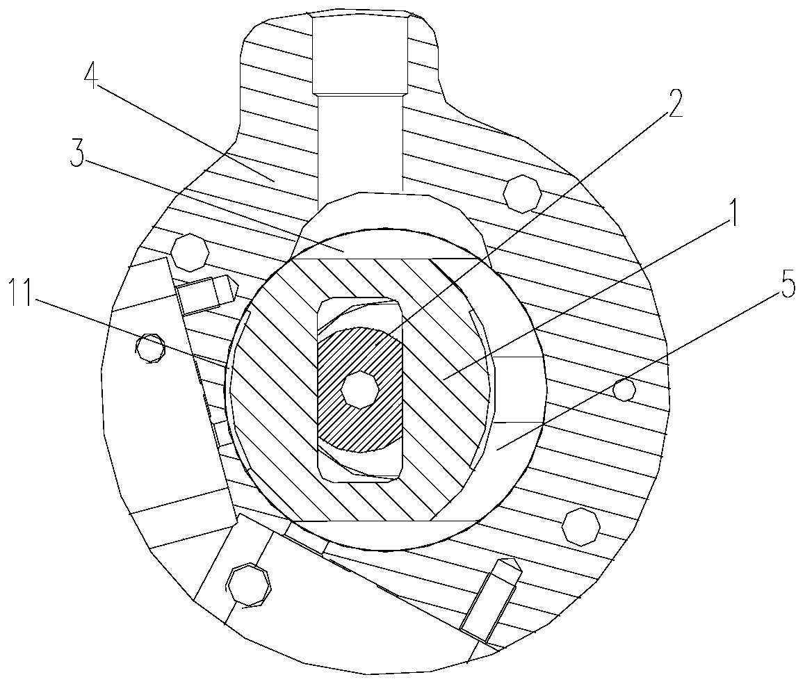
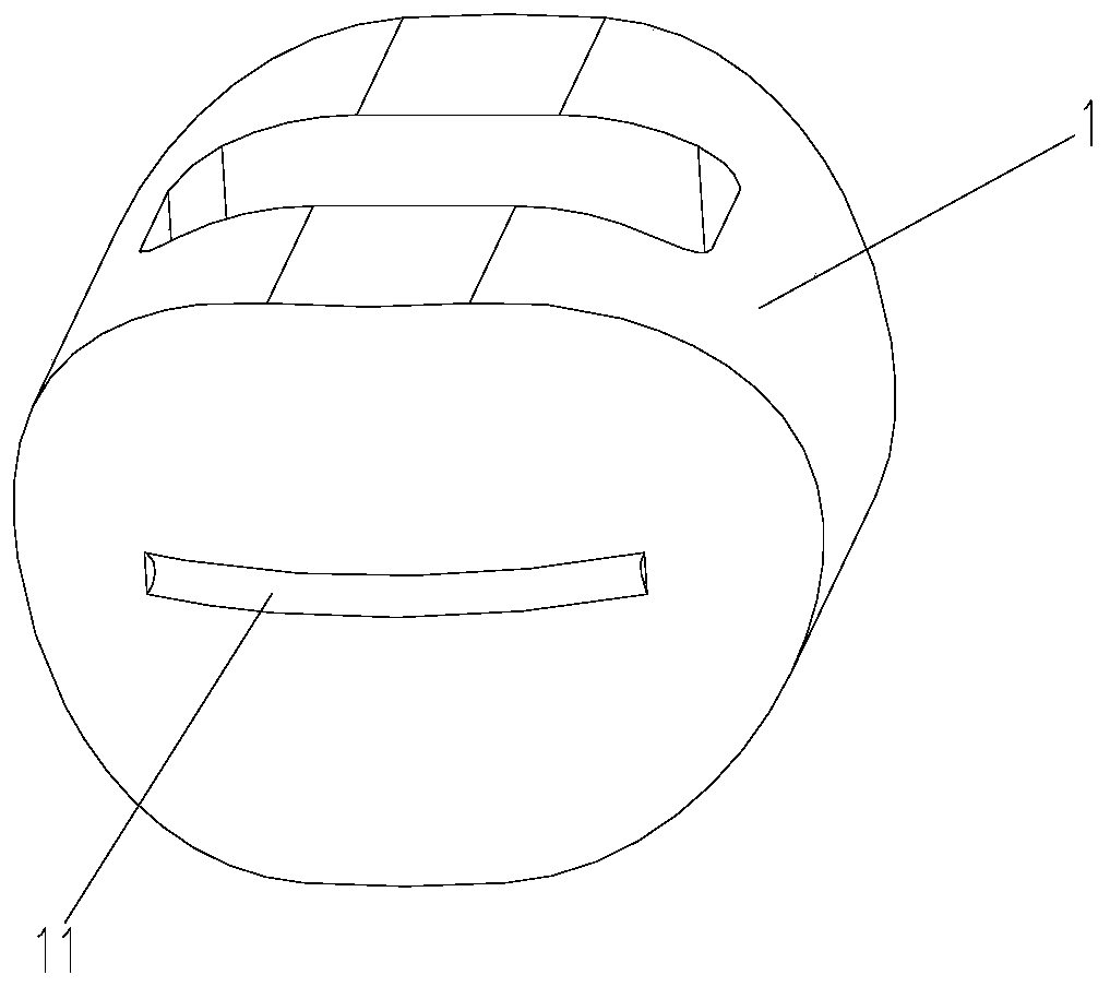
[0049] Such as Figure 1 to Figure 9 As shown, the pump body assembly includes a piston 1, a rotating shaft 2, a piston sleeve 3, and a cylinder 4. The rotating shaft 2 drives the piston 1 to reciprocate in the piston sleeve 3 while rotating; the cylinder, the piston sleeve 3 are located in the cylinder 4, and the piston 1 A compression chamber 5 is formed between the outer peripheral wall of the piston 1 and the inner wall of the cylinder 4 , and a pressure relief recess 11 is provided on the outer peripheral wall of the piston 1 or the inner wall of the cylinder, and the pressure relief recess 11 corresponds to the compression chamber 5 .

[0050] It should be noted that, in this embodiment, the pressure relief recess 11 is opened on the outer peripheral wall of the piston 1 .

[0051] Applying the technical scheme of the present invention, the piston sleeve 3 is located in the cylinder, and a compression chamber 5 is formed between the outer peripheral wall of the piston 1 an...

Embodiment 2

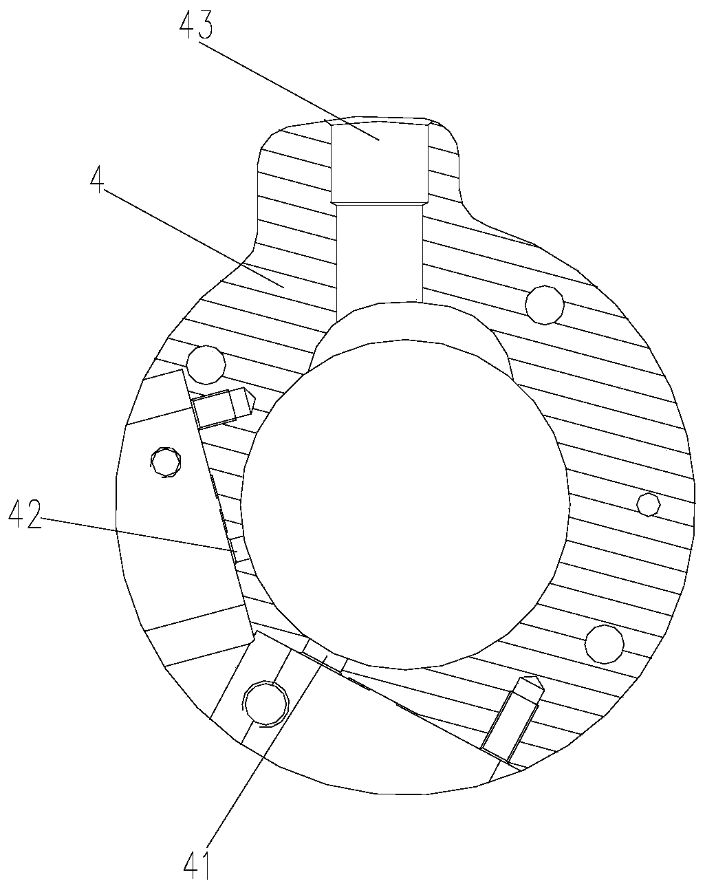
[0083] The main difference between this embodiment and the first embodiment is that the pressure relief recess 11 is provided on the cylinder 4 .

[0084] Specifically, the pump body assembly includes a piston 1, a rotating shaft 2, a piston sleeve 3, and a cylinder 4. The rotating shaft 2 drives the piston 1 to reciprocate in the piston sleeve 3 while rotating. The cylinder, the piston sleeve 3 is located in the cylinder 4, and the compression chamber 5 is formed between the outer peripheral wall of the piston 1 and the inner wall of the cylinder 4, and the inner wall of the cylinder 4 is provided with a pressure relief recess 11, and the pressure relief recess 11 corresponds to the compression chamber 5 .

[0085] Applying the technical solution of the present invention, the piston sleeve 3 is located in the cylinder, and a compression chamber 5 is formed between the outer peripheral wall of the piston 1 and the inner wall of the cylinder, and a pressure relief recess 11 is ...

Embodiment 3

[0088] The main difference between this embodiment and Embodiment 1 is that, as Figure 10 and Figure 11 As shown, the cross-section of the pressure relief groove is a rectangle, which is more convenient to process than a semicircle, and only needs to move the cutter head in one direction during the process.


PUM


Abstract

The invention provides a pump body assembly, heat exchange equipment, a fluid machine and an operation method of the fluid machine. The pump body assembly comprises a piston, a rotating shaft, a piston sleeve and an air cylinder; the rotating shaft performs reciprocating motion in the piston sleeve while driving the piston to rotate; the piston sleeve are located in the air cylinder; a compressioncavity is formed between the outer circumferential wall of the piston and the inner wall of the air cylinder; a pressure relief concave part is arranged on the outer circumferential wall of the piston or the inner wall of the air cylinder; and the pressure relief concave part corresponds to the compression cavity. With the pump body assembly of the invention adopted, over-compression occurring during the air exhausting of a pump body assembly in the prior art is alleviated.

Description

technical field [0001] The invention relates to the field of heat exchange systems, in particular to a pump body assembly, heat exchange equipment, fluid machinery and an operation method thereof. Background technique [0002] Chinese patent CN109595157A discloses the pump body structure of the rotary cylinder piston compressor and the rotary cylinder piston compressor. Its working principle is that the rotating shaft drives the piston to rotate, and the piston drives the piston sleeve to rotate in the cylinder. However, the piston only has relative reciprocating motion relative to the rotating shaft and the piston sleeve, and the two reciprocating motions are perpendicular to each other. During this process, suction, compression and exhaust are realized. During the process of suction, compression and exhaust, the radial distance between the piston and the inner diameter of the cylinder changes periodically. In the process of air intake, the radial distance between the pis...

Claims


Application Information

Patent Timeline
Patent Type & Authority Applications(China)
IPC IPC(8): F04C18/22F04C29/00
CPCF04C18/22F04C29/00F04C2240/20F04C2240/30F04B35/01F04C18/34F01C21/10F01C21/08F04C29/0021
Inventor 董明珠胡余生魏会军徐嘉杜忠诚任丽萍杨森李直张培林梁社兵史正良张荣婷丁宁
Owner GREE ELECTRIC APPLIANCES INC
Why Eureka
Try Eureka