Range hood

A technology for range hoods and fan racks, which is applied in the direction of removing oil fumes, mechanical equipment, machines/engines, etc. It can solve the problems of not eliminating associated eddy currents, lack of diversion surfaces, increased noise, etc., and reduce local backflow and eddy kinetic energy Loss, avoid eddy current, reduce noise effect

Active Publication Date: 2020-03-24
NINGBO FOTILE KITCHEN WARE CO LTD
View PDF7 Cites 10 Cited by
  • Summary
  • Abstract
  • Description
  • Claims
  • Application Information

AI Technical Summary

Problems solved by technology

There are obvious cross-sectional mutations and lack of diversion surfaces between the collector of the range hood and the front end ring of the impeller. There are two obvious "typhoon eyes", one large and one small, at the a...

Method used


Image

  • Range hood
  • Range hood
  • Range hood

Examples


Embodiment 1

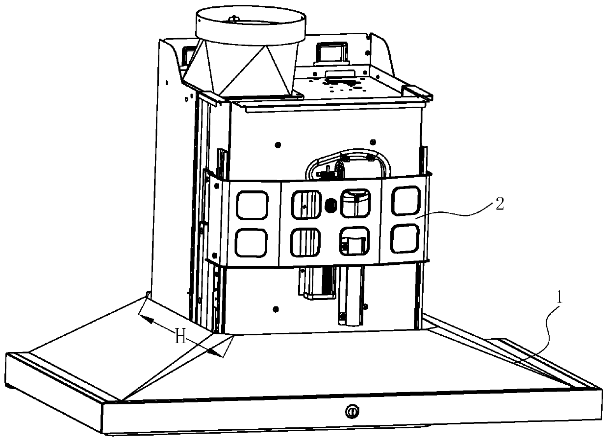
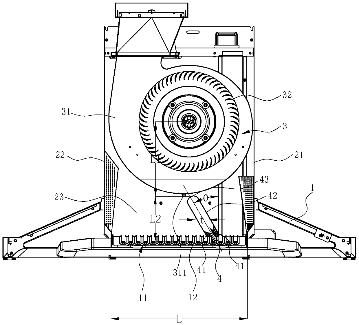
[0033] see Figure 1 ~ Figure 3 , a range hood, including a smoke collection hood 1, a fan frame 2 arranged above the smoke collection hood 1, and a fan system 3 arranged in the fan frame 2. The blower system 3 includes a volute 31 and an impeller 32 arranged in the volute 31 .

[0034] A vortex and noise reducer 4 is arranged inside the fan frame 2 , and the vortex and noise reducer 4 is arranged below the fan system 3 . An air inlet 11 is opened on the smoke collecting hood 1 , and the vortex and noise reducer 4 is located above the air inlet 11 .

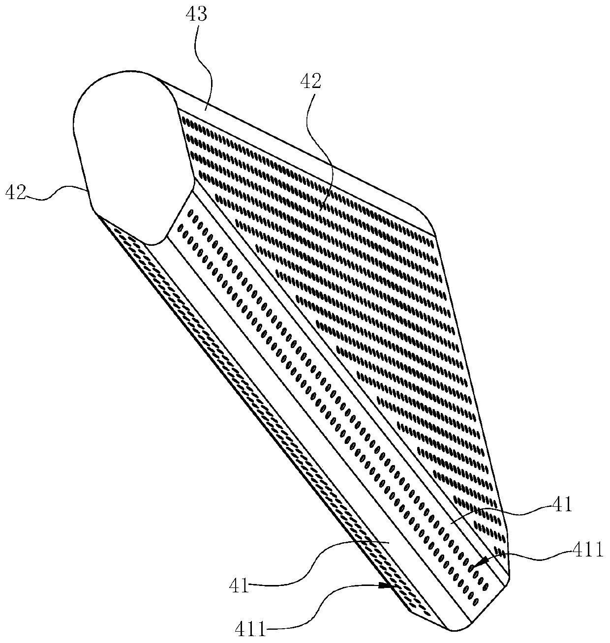
[0035] The vortex and noise reducer 4 is a cylinder with a windward wall 41 at the bottom, a flow guide wall 42 at the side and an airflow separation wall 43 at the top. There are two windward wall surfaces 41 , one ends of the two windward wall surfaces 41 are connected to each other, and the other ends gradually extend upward in directions away from each other. The windward wall surface 41 gradually slopes downward from fron...

Embodiment 2

[0060] see Figure 7 , In this embodiment, the difference from the first embodiment above is that in order to further reduce noise and solve the problem of oil conduction, the vortex and noise reducer 4 is given the function of conducting oil and reducing the noise of the oil leakage nozzle. For this reason, the vortex and noise reducer 4 is made into a hollow structure, and the oil leakage nozzle 311 at the bottom of the volute 31 of the fan system 3 is connected with the vortex and noise reducer 4, and is close to the fan frame below the vortex and noise reducer 4. The position of the rear plate 23 of 2 is open, so that the oil is guided to the rear plate of the fan frame 2 at the opening. At this time, the hollow vortex and noise reducer 4 becomes an oil guide groove at the same time, so that the oil leakage nozzle 311 can be avoided. The oil inside changes the descending route under the impact of the upper and lower airflows, causing oil droplets to drop through the oil ne...

Embodiment 3

[0062] In this embodiment, the difference from the second embodiment above is that the oil leakage nozzle 311 and the vortex and noise reducer 4 are connected through a noise reduction pipe 312, and a noise reduction hole is opened on the noise reduction pipe 312, and the diameter of the noise reduction hole is 5≥φ≥0.5, more preferably φ=1.5, the vortex and noise reducer 4 is in a sealed state, and communicates with the outside world only through the noise reduction hole on the wall of the noise reduction pipe 312, and the noise reduction pipe 312 extends to the fan On the rear plate 23 of the frame 2, the high-speed gas and grease ejected from the oil leakage nozzle 311 enter the noise reduction pipe 312, and the grease is guided to the rear plate 23 of the fan frame 2 along the noise reduction pipe 312, which can avoid leakage. The oil in the oil nozzle 311 changes its descending route under the impact of the upper and lower airflows, causing oil droplets to drip through the ...


PUM


Abstract

The invention discloses a range hood, which comprises a fan frame and a fan system arranged in the fan frame. The fan system comprises a volute and an impeller; a vortex eliminating and noise reducingdevice is arranged in the fan frame; the vortex eliminating and noise reducing device is a cylinder; the vortex eliminating and noise reducing device has windward wall faces located at the bottom, flow guide wall faces located on the side face and an airflow separation wall face located at the top. One ends of the two windward wall faces are connected, and the other ends of the two windward wallfaces extend away from each other; the flow guide wall faces extend upwards in the longitudinal direction from the ends, away from each other, of the windward wall faces; and the airflow separation wall face is connected between the top ends of the two flow guide wall faces. The vortex eliminating and noise reducing device deflects relative to the vertical direction and has an inclination angle theta, and the deflection direction of the vortex eliminating and noise reducing device is opposite to the rotating direction of the impeller. Compared with the prior art, the range hood has the advantages that the deflection of the vortex eliminating and noise reducing device is used for eliminating obvious air inlet vortexes in the fan frame, so that local backflow and vortex kinetic energy loss caused by vortexes are reduced, and noise is reduced.

Description

technical field [0001] The invention relates to a cooking fume purifying device, in particular to a range hood. Background technique [0002] The range hood has become one of the indispensable kitchen appliances in modern families. The range hood works by using the principle of fluid dynamics. Grease particles. The centrifugal fan includes a volute, an impeller installed in the volute and a motor that drives the impeller to rotate. When the impeller rotates, a negative pressure suction is generated in the center of the fan, and the oil fume under the range hood is sucked into the fan, and after being accelerated by the fan, it is collected by the volute and guided out of the room. [0003] The air intake method of the multi-blade centrifugal fan is not uniform like that of the axial flow fan. Especially after it is installed in the fan frame box, there is a more obvious vortex in the air intake area. Macroscopically speaking, the vortex is a reality of turbulent flow. It ...

Claims


Application Information

Patent Timeline
IPC IPC(8): F04D29/66F04D29/42F04D29/063F24C15/20
CPCF04D29/063F04D29/4233F04D29/663F04D29/667F24C15/20
Inventor 王发银何立博
Owner NINGBO FOTILE KITCHEN WARE CO LTD
Why Eureka
Try Eureka