Partial discharge simulation test system and method based on oscillatory waves
A technology of partial discharge and simulation testing, which is applied in the direction of testing dielectric strength, measuring electricity, measuring devices, etc. It can solve the problems of waveforms that are difficult to identify, unfavorable to grasp, and cannot withstand high voltage, etc., to achieve the effect of avoiding pollution flashover
- Summary
- Abstract
- Description
- Claims
- Application Information
AI Technical Summary
Problems solved by technology
Method used
Image
Examples
Embodiment 1
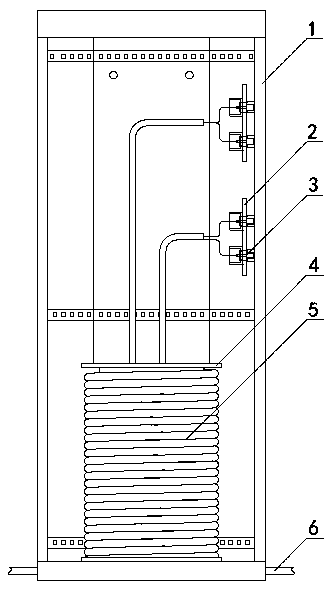
[0049] Such as figure 1 As shown, a partial discharge simulation test system based on oscillating waves includes a vertically placed rectangular housing 1, a cable winding part 4 is arranged at the center of the bottom of the inner cavity of the housing 1, and the cable winding part 4 is wound There is a cable 5, and the cable 5 is a section of cable without partial discharge defects. The two ends of the cable 5 connector are drawn out as cable connectors 6 from the opposite sides of the shell 1 bottom respectively.
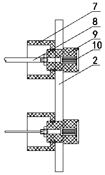
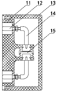
[0050] In this embodiment, any two positions in the cable 5 are set as test points, and the cable inner core and sheath (ground terminal) at the test points are drawn out respectively through wires and connected to the test joint mechanism 3, and the test joint The mechanism 3 is fixed on the side of the housing 1 through the joint fixing plate 2 . On the side of the housing 1 , there are two test joint mechanisms 3 arranged from top to bottom, which are respec...
Embodiment 2
[0081] The difference between this embodiment and embodiment 1 is: as Figure 7 As shown, in this embodiment, there is only one test point in the cable 5, so a test connector mechanism 3 is provided correspondingly, and the cable inner core and sheath (ground terminal) at the test point are also led out through wires And connected to the test joint mechanism 3, the test joint mechanism 3 is fixed on the side of the shell 1 through the joint fixing plate 2.
Embodiment 3
[0083] The difference between this embodiment and embodiment 1 is: as Figure 8As shown, a discharge tip 22 is arranged in the first insulator 19 in the partial discharge test module 15 of this embodiment, and one end of the discharge tip 22 is connected to the corresponding discharge electrode 18, and its tip enters the discharge after passing through the first insulator 19. within the gap 20. The test of tip discharge can be realized through the partial discharge test module 15 of this embodiment.
PUM
 Abstract
Description
Claims
Application Information
 - R&D
- Intellectual Property
- Life Sciences
- Materials
- Tech Scout
- Unparalleled Data Quality
- Higher Quality Content
- 60% Fewer Hallucinations
Browse by: Latest US Patents, China's latest patents, Technical Efficacy Thesaurus, Application Domain, Technology Topic, Popular Technical Reports.
© 2025 PatSnap. All rights reserved.Legal|Privacy policy|Modern Slavery Act Transparency Statement|Sitemap|About US| Contact US: help@patsnap.com


