Service life testing machine for tubular motor

A life test, tubular motor technology, applied in the direction of motor generator testing, electrical measuring instrument parts, measuring electricity, etc., can solve the problem that the load mechanism cannot use the tubular motor, the test effect is poor, and the installation is difficult, etc. Clamping stability and easy installation

Inactive Publication Date: 2020-03-24
永昌控股集团有限公司
View PDF9 Cites 2 Cited by
  • Summary
  • Abstract
  • Description
  • Claims
  • Application Information

AI Technical Summary

Problems solved by technology

However, due to the large difference between the shape of the tubular motor and the ordinary motor, the conventional motor life testing machine cannot complete the installation test of the tubular motor, and because the outer diameters of different tubular motors are different, and the overall length of the motor also varies with the manufacturer's needs. Adjustment, the manufacturer needs to set up a set of corresponding fixtures according to different sizes of tubular motors during installation, thus increasing the difficulty of clamping the tube clamp motor
In addition, due to the difference in the shape of the tubular motor, the load mechanism used in the conventional motor test cannot be used in the tubular motor, thereby reducing the test effect on the tubular motor
Therefore, existing life test methods for tubular motors have the problems of difficult installation and poor test results

Method used


Image

  • Service life testing machine for tubular motor
  • Service life testing machine for tubular motor
  • Service life testing machine for tubular motor

Examples


Embodiment Construction

[0018] The present invention will be further described below in conjunction with the accompanying drawings and embodiments, but not as a basis for limiting the present invention.

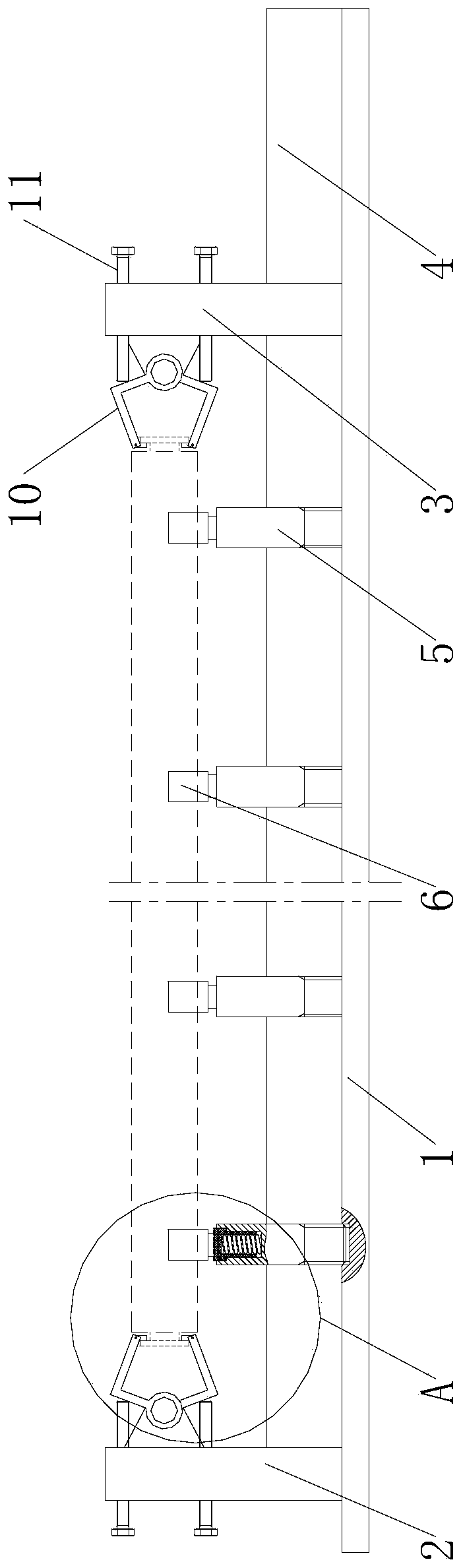
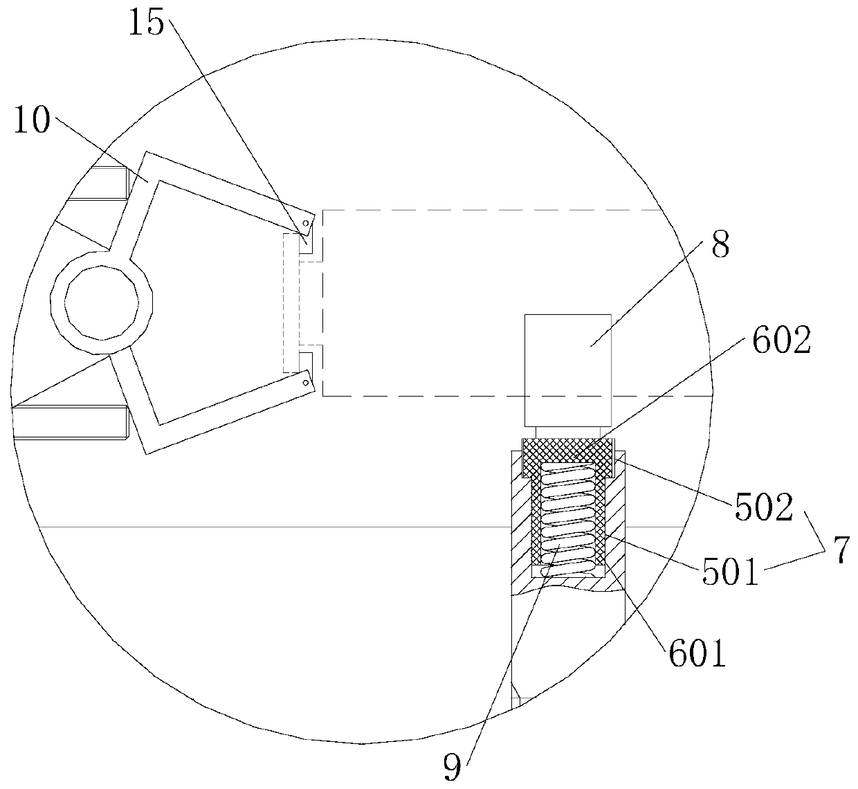
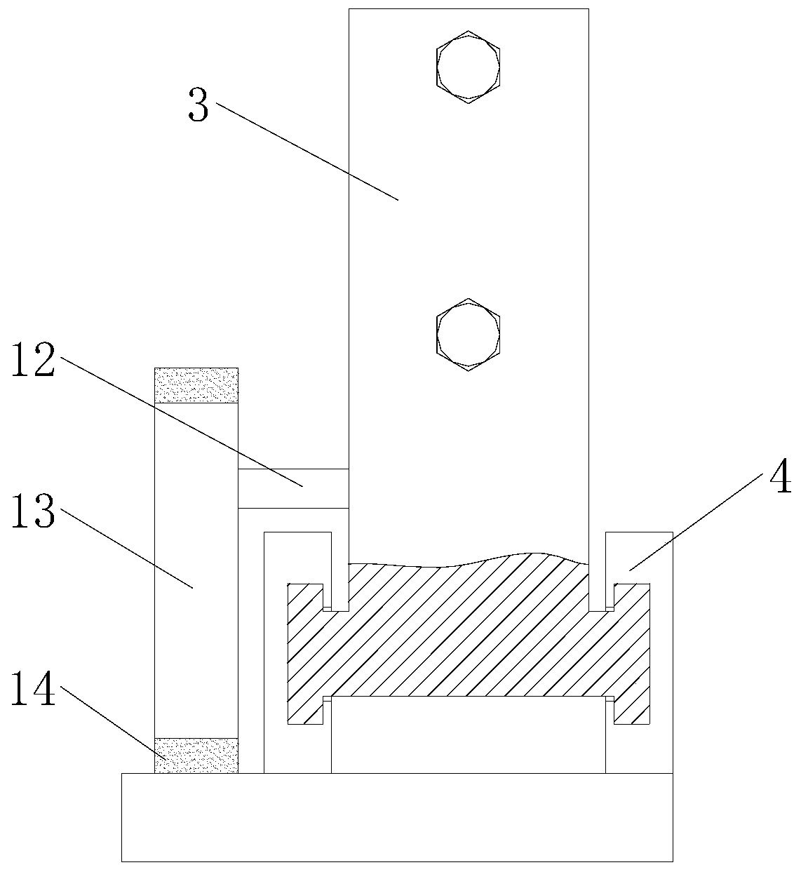
[0019] Example. A tubular motor life testing machine, constituted as figure 1 As shown, the test platform 1 is included, the test platform 1 is respectively provided with a fixed seat 2 and a movable seat 3, the outer side of the fixed seat 2 is provided with a drive power supply, and the two sides of the lower end of the movable seat 3 are connected to the test platform 1 through the guide rail 4, and the fixed seat 2 and the moving base 3 are provided with a clamping assembly, one side of the moving base 3 is provided with a limit assembly, and a pressure assembly is provided on the test platform 1 between the fixed base 2 and the moving base 3, and the pressure assembly is located in the vertical direction. The middle position of the guide rails 4 on both sides; the pressure assembly includes a ...


PUM


Abstract

The invention discloses a service life testing machine for a tubular motor. The service life testing machine comprises a test platform, a fixed base and a movable base are separately arranged on the test platform, and the two sides at the lower end of the movable base are connected with the test platform through guide rails. Clamping assemblies are arranged on the fixed base and the movable base,a limiting assembly is arranged at one side of the movable base, and a pressure assembly is arranged on the test platform between the fixed base and the movable base and comprises a positioning rod and a telescopic rod which are buckled with each other. The lower end of the positioning rod is in threaded connection with the test platform, the upper end of the positioning rod is provided with a placement cavity, and the top of the telescopic rod is provided with a pressing plate located above a first connecting part. A pressure spring is arranged in the placement cavity, the bottom of the pressure spring is attached to the bottom of the placement cavity, and the top of the pressure spring is attached to the upper end of the telescopic rod. The service life testing machine has the characteristics of convenient installation and good test effect.

Description

technical field [0001] The invention relates to a motor testing mechanism, in particular to a tubular motor life testing machine. Background technique [0002] Tubular motors are often used in electric rolling doors and electric blinds due to their shape and rotation mode. The same as the production method of ordinary motors, the tubular motor also needs to pass the life test after production. By clamping both ends of the tubular motor, it keeps rotating after clamping to test the working life and rotation stability of the motor. . However, due to the large difference between the shape of the tubular motor and the ordinary motor, the conventional motor life testing machine cannot complete the installation test of the tubular motor, and because the outer diameters of different tubular motors are different, and the overall length of the motor also varies with the manufacturer's needs. Due to the adjustment, the manufacturer needs to set up a set of corresponding fixtures acc...

Claims


Application Information

Patent Timeline
Patent Type & Authority Applications(China)
IPC IPC(8): G01R31/34G01R1/04
CPCG01R1/0425G01R31/343
Inventor 孙豪远江林飞汪旭亮
Owner 永昌控股集团有限公司
Why Eureka
Try Eureka