Display panel and preparation method thereof

A display panel and one-sided technology, applied in television, optics, instruments, etc., can solve problems such as insufficient absorption rate of OCA optical adhesive layer difference, air bubbles in the camera area, etc., to improve bonding yield, quality, and light transmittance Effect

Inactive Publication Date: 2020-03-24
WUHAN CHINA STAR OPTOELECTRONICS TECH CO LTD
View PDF3 Cites 15 Cited by
  • Summary
  • Abstract
  • Description
  • Claims
  • Application Information

AI Technical Summary

Problems solved by technology

[0007] The purpose of the present invention is to provide a display panel and its preparation method to solve the technical problem that the lack of step absorption rate of the OCA optical adhesive layer in the prior art easily leads to bubbles around the imaging area

Method used


Image

  • Display panel and preparation method thereof
  • Display panel and preparation method thereof
  • Display panel and preparation method thereof

Examples


Embodiment 1

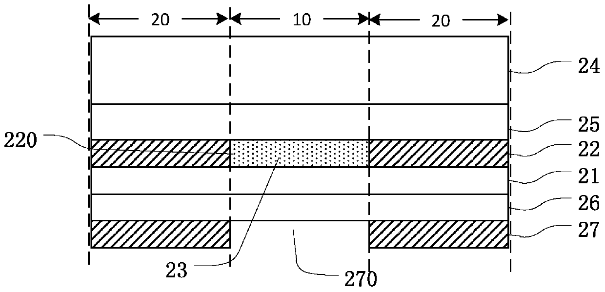
[0036] Such as figure 2 As shown, this embodiment provides a display panel, including an imaging area 10 and a display area 20 , and the display area 20 surrounds the imaging area 10 . The display panel includes a first substrate 21 , a first polarizer 22 , a liquid optical adhesive layer 23 , a cover plate 24 and a solid optical adhesive layer 25 .

[0037] The first substrate 21 is a color filter substrate, and generally includes a substrate, a black matrix (BlackMatrix, BM) and a color filter layer formed on the substrate. Wherein, the color filter layer includes a plurality of filter units of different colors, such as red, green and blue green light units formed by using red, green and blue photosensitive resins respectively, and the black matrix is ​​used to define the space between each filter unit. In order to prevent light leakage between adjacent filter units, the edges of the filter units are usually overlapped on the black matrix, and each filter unit is not forme...

Embodiment 2

[0051] Such as Figure 4 As shown, this embodiment provides a display panel, including an imaging area 10 and a display area 20 , and the display area 20 surrounds the imaging area 10 . The display panel includes a first substrate 21 , a first polarizer 22 , a liquid optical adhesive layer 23 , a cover plate 24 and a solid optical adhesive layer 25 .

[0052] The first substrate 21 is a color filter substrate, and generally includes a substrate, a black matrix (BlackMatrix, BM) and a color filter layer formed on the substrate. Wherein, the color filter layer includes a plurality of filter units of different colors, such as red, green and blue green light units formed by using red, green and blue photosensitive resins respectively, and the black matrix is ​​used to define the space between each filter unit. In order to prevent light leakage between adjacent filter units, the edges of the filter units are usually overlapped on the black matrix, and each filter unit is not forme...


PUM


Abstract

The invention provides a display panel and a preparation method thereof. The display panel comprises a camera shooting area, a display area surrounding the camera shooting area, a first substrate, a first polarizer, a liquid optical adhesive layer, a cover plate and a solid optical adhesive layer. The first polaroid is arranged on one surface of the first substrate; the first polaroid is providedwith a first slotted hole corresponding to the camera shooting area; the first slotted hole is filled with the liquid optical adhesive layer; the cover plate is connected to the face, away from the first substrate, of the first polaroid in a covering mode. The solid optical adhesive layer is at least arranged between the cover plate and the first polaroid. The invention has the technical effects;according to the display panel and the preparation method thereof provided by the invention, the liquid optical adhesive is used for replacing the solid optical adhesive to fill the slotted hole of the corresponding camera shooting area, so that the phenomenon of bubbles when the slotted hole is filled with the solid optical adhesive is avoided, the laminating yield is improved, the light absorption rate of the optical adhesive at the slotted hole is improved, the light transmittance of the camera shooting area is improved, and the quality of the display panel is further improved.

Description

technical field [0001] The invention relates to the display field, in particular to a display panel and a preparation method thereof. Background technique [0002] With the development of liquid crystal display technology, especially the development of full screen technology, a hole structure is made in the backlight unit (BLU) of the display device. The in-plane hole structure can be a camera area of ​​a camera, which is applied to a display panel, such as a mobile phone. The in-plane hole structure is divided into two types: blind hole and through hole. Compared with the through hole structure, the blind hole structure has the advantage of high production efficiency. [0003] In the prior art, a liquid crystal display device includes a display panel, an IC circuit, a flexible printed circuit board (Flexible Printed Circuit Board) and a backlight module. The backlight module includes a light source, a light guide plate, a diffusion sheet, an enhancement sheet and a backpl...

Claims


Application Information

Patent Timeline
Patent Type & Authority Applications(China)
IPC IPC(8): G02F1/1333G02F1/1335H04N5/225
CPCG02F1/1333G02F1/133528H04N23/57
Inventor 张鹏
Owner WUHAN CHINA STAR OPTOELECTRONICS TECH CO LTD
Why Eureka
Try Eureka