Backlight module and display device

A technology for backlight modules and display devices, applied in optics, nonlinear optics, instruments, etc., can solve problems such as the inability to display RGB color images normally, the inability to prevent RGB color resistance, etc. Full screen display to ensure the effect of ductility

Active Publication Date: 2021-10-08
WUHAN CHINA STAR OPTOELECTRONICS TECH CO LTD
View PDF9 Cites 0 Cited by
  • Summary
  • Abstract
  • Description
  • Claims
  • Application Information

AI Technical Summary

Problems solved by technology

However, there is no color resistance scheme in the through hole area, and RGB color images cannot be displayed normally; and in order to ensure the imaging effect of the camera, RGB color resistance cannot be prevented on the color filter substrate side, because RGB color resistance will absorb light

Method used


Image

  • Backlight module and display device
  • Backlight module and display device

Examples


Embodiment Construction

[0020] In order to better understand the content of the present invention, the present invention will be further described through specific examples below, but the implementation and protection scope of the present invention are not limited thereto.

[0021] The following description of the embodiments refers to the accompanying drawings to illustrate specific embodiments in which the invention may be practiced. The directional terms mentioned in the present invention, such as "up", "down", "front", "back", "left", "right", "top", "bottom", etc., are only for reference to the attached drawings. direction. Therefore, the directional terms used are used to illustrate and understand the present invention, but not to limit the present invention.

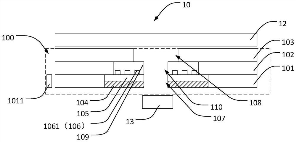
[0022] Please refer to figure 1 As shown, the first embodiment of the present invention provides a backlight module 100, the backlight module 100 includes a substrate 104, a reflection sheet 101, a light guide plate 102, a diffusion fi...


PUM


Abstract

The invention provides a backlight module and a display device. The backlight module includes a substrate, a reflection sheet, a light guide plate, a diffusion film, a reflection layer, a transparent film layer, and a backlight source. In the invention, the substrate is spliced ​​at the reflection sheet, and At the junction of the substrate and the reflective sheet, due to the high reflectivity of the reflective layer, the reflective layer can effectively replace the function of the reflective sheet, thereby ensuring the ductility of light and reducing the requirements for assembly accuracy. In addition, the white light emitting unit can be used at the splicing place, and the MiniLED can be individually controlled to realize the difference in the light intensity of the MiniLED at different positions, thereby solving the phenomenon of black edges and dark edges at the splicing place, and can better realize a comprehensive screen display. Compensate the phenomenon of uneven light emission of the backlight module due to digging holes.

Description

technical field [0001] The invention relates to the field of display technology, in particular to a backlight module and a display device. Background technique [0002] With the improvement of the overall process design capabilities of mobile phones, consumers' aesthetics are constantly being guided and improved. Therefore, the overall trend of mobile phone screens has gradually shifted to the direction of full-screen design. Therefore, in display screens such as chip-on-film (COF), ultra-narrow bezel, and heterosexual screens, the design capabilities and process capabilities of full-screen related indicators have been continuously improved in less than a year, and the screen-to-body ratio of the screen has also increased from 80. % gradually increased to 97%. However, with the rapid improvement of the above capabilities, it has reached a relative bottleneck period. Therefore, the in-screen hole-digging technology has emerged as the times require. In-plane digging can furth...

Claims


Application Information

Patent Timeline
Patent Type & Authority Patents(China)
IPC IPC(8): G02F1/13357
CPCG02F1/133603G02F1/133605G02F1/133606G02F1/133607G02B6/009G02B6/0088G02B6/0076G02B6/0055G02F1/1336G02F1/133553G02B6/0068G02B6/0086
Inventor 刘凡成王超
Owner WUHAN CHINA STAR OPTOELECTRONICS TECH CO LTD
Why Eureka
Try Eureka