MMC topology containing partial energy storage elements and steady-state operation control method of MMC topology

A technology of energy storage components and control methods, applied to electrical components, output power conversion devices, reducing/preventing power oscillations, etc., can solve problems such as lack of AC and DC side power conversion capabilities

Active Publication Date: 2020-03-24
STATE GRID HUNAN ELECTRIC POWER +2
View PDF2 Cites 2 Cited by
  • Summary
  • Abstract
  • Description
  • Claims
  • Application Information

AI Technical Summary

Problems solved by technology

However, it does not have the power conversion capability of AC and DC side

Method used


Image

  • MMC topology containing partial energy storage elements and steady-state operation control method of MMC topology
  • MMC topology containing partial energy storage elements and steady-state operation control method of MMC topology
  • MMC topology containing partial energy storage elements and steady-state operation control method of MMC topology

Examples


Embodiment 1

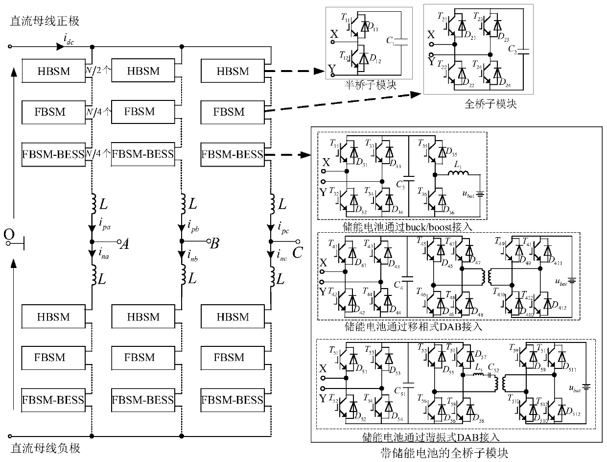
[0058] This embodiment discloses a MMC topology containing some energy storage elements, each bridge arm includes a half-bridge sub-module (HBSM), a common full-bridge sub-module (FBSM) and an energy storage element (battery energy storage system, BESS ) of the full-bridge sub-module (FBSM-BESS), the three sub-modules are N / 2, N / 4 and N / 4 respectively; the HBSM and FBSM are collectively referred to as common sub-modules, and the specific topology Such as figure 1 shown.

Embodiment 2

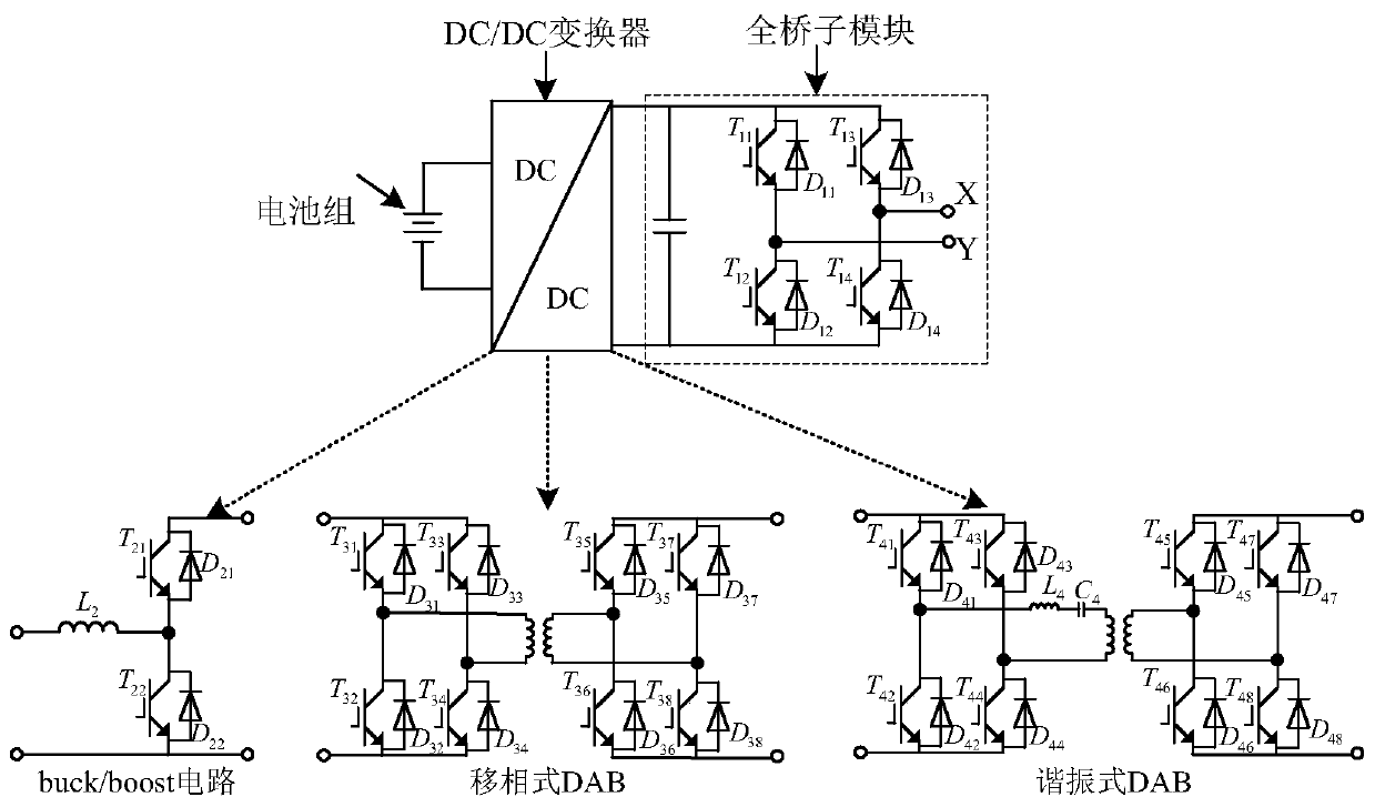
[0060] In this embodiment, on the basis of Embodiment 1, the full-bridge sub-module containing energy storage elements adopts the following figure 2 The topology shown includes a battery pack, a full-bridge sub-module and an intermediate DC / DC converter; the DC / DC converter can be a buck / boost non-isolated converter, consisting of two full-bridge units and a DC A phase-shifting dual active bridge converter (DAB) composed of a / DC transformer and a resonant dual active bridge converter composed of two full bridge units, a DC / DC transformer, an energy storage capacitor and a resonant inductor.

Embodiment 3

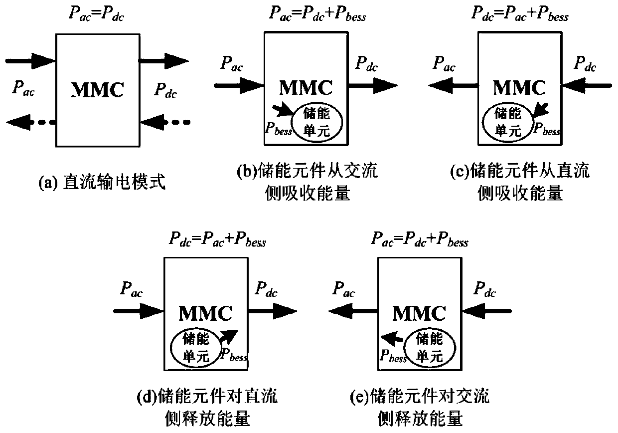
[0062] This embodiment discloses a steady-state operation control method of an MMC containing part of the energy storage element, wherein the MMC containing part of the energy storage element adopts the topological structure in Embodiment 1 or 2, and through the steady-state operation control method, the MMC containing part of the energy storage The MMC of the component can work in three modes: the direct current transmission mode, the energy storage element absorption energy mode in the MMC topology, and the energy storage element release energy mode in the MMC topology. image 3 As shown, it can be divided into DC transmission mode, energy storage element absorbing energy mode from the AC side, energy storage element absorbing energy mode from the DC side, energy storage element releasing energy mode to the DC side, and energy storage element releasing energy mode to the AC side. Five modes. For the convenience of subsequent analysis, according to the difference in the speci...


PUM


Abstract

The invention discloses an MMC topology containing partial energy storage elements and a steady-state operation control method of the MMC topology. The MMC topology is characterized in that each bridge arm comprises a plurality of sub-modules connected in series and a bridge arm inductor. The sub-modules comprise an HBSM, an FBSM and an FBSM-BESS, that is, a half-bridge sub-module, a common full-bridge sub-module and a full-bridge sub-module containing an energy storage element. And the numbers of the HBSM, the FBSM and the FBSM-BESS in each bridge arm are respectively N / 2, N / 4 and N / 4. The MMC topology has AC-DC side power conversion capability, power oscillation suppression capability and good frequency support capability, has low requirements on the capacity of the energy storage device, and has small influence on the efficiency of the converter.

Description

technical field [0001] The invention belongs to the technical field of multi-level power electronic converters, and more specifically relates to an MMC topology including a part of energy storage elements and a steady-state operation control method thereof. Background technique [0002] With good DC short-circuit fault ride-through capability, low cost and high operating efficiency, the bridge arm consists of a full bridge sub-module (Full Bridge Sub-module, FBSM) and a half bridge sub-module (Half Bridge Sub-module, HBSM ) 1:1 hybrid MMC (modular multilevel converter), has become one of the main choices for flexible HVDC converter topologies. However, the hybrid MMC cannot realize the decoupling of AC and DC side power, and cannot provide sufficient damping to suppress power oscillation under transient conditions, and has limited ability to support AC grid frequency. [0003] Because the energy storage device has a separate battery pack, it has functions such as smooth tra...

Claims


Application Information

Patent Timeline
IPC IPC(8): H02M7/483H02J3/24H02J3/32
CPCH02J3/24H02J3/32H02M7/483H02M7/4835
Inventor 郭思源严亚兵陈远扬
Owner STATE GRID HUNAN ELECTRIC POWER
Why Eureka
Try Eureka