A waste gas treatment system used in electroplating process and its working method

A technology for waste gas treatment and electroplating process, which is applied in separation methods, chemical instruments and methods, and dispersed particle separation. The effect of efficiency

Active Publication Date: 2021-09-21
安徽宏远电镀表面处理有限公司
View PDF0 Cites 0 Cited by
  • Summary
  • Abstract
  • Description
  • Claims
  • Application Information

AI Technical Summary

Problems solved by technology

[0005] However, it cannot solve the problem of treating the exhaust gas immediately after extracting the exhaust gas. If the exhaust gas overflows during the transmission process, it will affect the environment and human safety in the environment.

Method used


Image

  • A waste gas treatment system used in electroplating process and its working method
  • A waste gas treatment system used in electroplating process and its working method
  • A waste gas treatment system used in electroplating process and its working method

Examples


Embodiment 1

[0047] refer to Figure 1-4 as an example.

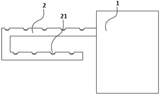
[0048] A waste gas treatment system used in an electroplating process, comprising: a treatment chamber (1) and a processor.

[0049] The exhaust gas treatment system also includes an air extraction module and a reaction module. The processing chamber is provided with a gas guide port, and the gas guide port passes through the processing chamber.

[0050] The air extraction module includes a circulating pump and an air extraction pipeline 2 . The air extraction pipeline 2 is arranged outside the processing chamber, the air extraction pipeline 2 is connected to the circulation pump, and the circulation pump is connected to the processor. The processor outputs an on signal or an off signal to the circulation pump, and the circulation pump is turned on or off according to an instruction of the processor. The circulation pump draws the electroplating waste gas through the suction pipe 2 .

[0051]The circulation pump is connected to...

Embodiment 2

[0067] refer to Figure 5-6 as an example.

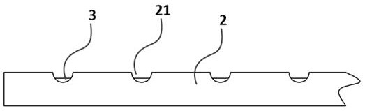
[0068] This embodiment is basically the same as the above-mentioned embodiment, the difference is that, as a preferred mode of this embodiment, the processing chamber 1 includes a processing module, and the processing module includes a reaction pool 5 and a ventilation pipe 4. The air extraction inner pipeline 3 is in communication with the ventilation pipe 4, and the ventilation pipe 4 is in communication with the reaction pool 5. Reaction chemicals are stored in the reaction pool 5, and the reaction chemicals are used to react with the electroplating waste gas.

[0069] The electroplating waste gas in the exhaust inner pipeline 3 is output to the ventilation pipe 4, and the ventilation pipe 4 introduces the electroplating waste gas into the reaction tank 5. The electroplating exhaust gas reacts with the solution in the reaction tank 5 .

[0070] As a preferred manner of this embodiment, the reaction pool 5 includes at least two...

Embodiment 3

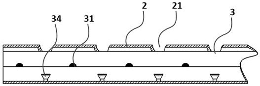
[0087] This embodiment is basically the same as the above-mentioned embodiment, the difference is that, as a preferred mode of this embodiment, a recovery module is arranged in the air extraction pipeline 2, and the recovery module includes a sealing layer, a recovery port, and a drainage tube . The sealing layer is arranged on the bottom of the air extraction pipeline 2, the sealing layer is used to seal the bottom of the air extraction pipeline 2, the recovery port is arranged on the sealing layer, and the recovery port is used to collect the The liquid in the suction pipeline 2 is described. The drainage tube is arranged in the sealing layer, and the drainage tube guides the liquid in the sealing layer to the waste liquid collection place.

[0088] The sealing layer is used to separate the liquid from the electroplating waste gas, the recovery port is used for the infiltration of the liquid, and the drainage tube is embedded in the suction pipe 2 to drain the liquid.


PUM


Abstract

The invention relates to a waste gas treatment system used in an electroplating process and a working method thereof, comprising: a treatment chamber and a processor; the treatment chamber includes an air extraction module and a reaction module; The air port runs through the processing chamber; the air extraction module includes a circulating pump and an air extraction pipeline; the air extraction pipeline is provided with a number of first air inlets; the air extraction pipeline is provided with an inner air extraction pipeline, and the air extraction pipeline is sleeved outside the inner air extraction pipeline , a second air inlet is provided on the inner pipeline of the air extraction; the reaction module includes a photochemical reaction device, an oxidation device, and a catalyst layer; Pass through the catalyst layer and react with the catalyst layer; the photochemical reaction device is arranged around the inner side of the second air inlet; the oxidation device is arranged in the inner pipeline of the air extraction, the oxidation device includes an oxidation nozzle and an infusion pipeline, and the oxidation nozzle is connected to the processor.

Description

technical field [0001] The invention relates to electroplating exhaust gas treatment, in particular to an exhaust gas treatment system used in the electroplating process and a working method thereof. Background technique [0002] Electroplating is a small but essential basic technological industry in the national economy, and it is also a heavy polluting industry. The waste gas, waste water, and waste residue produced by electroplating seriously affect people's life and health. [0003] Various additives and complexes in the formulation of the electroplating process solution make people dazzled. In addition, there are still a few types of plating that cannot eliminate cyanide in the short term, so cyanide-containing electroplating still exists in some special product electroplating. Especially the surface treatment before plating and the increase of the amount of acid and alkali during deplating will inevitably generate a large amount of waste gas in the electroplating prod...

Claims


Application Information

Patent Timeline
Patent Type & Authority Patents(China)
IPC IPC(8): B01D53/75B01D53/78B01D53/74B01D53/86
CPCB01D53/74B01D53/75B01D53/78B01D53/86
Inventor 金驰
Owner 安徽宏远电镀表面处理有限公司
Why Eureka
Try Eureka