
Stirring head with depth variation for stirring area of friction stir welding

A technology of friction stir welding and stirring zone, which is used in welding equipment, manufacturing tools, non-electric welding equipment, etc., can solve the problems of stirring in the stirring zone, the friction effect is not good, and the welded joints are prone to defects, so as to avoid tunnel-type defects, Increase the effect of stirring and heat generation, and improve the effect of stirring force

Inactive Publication Date: 2020-03-27
HUNAN JOINFRONT WELDING TECH
View PDF5 Cites 0 Cited by
  • Summary
  • Abstract
  • Description
  • Claims
  • Application Information

AI Technical Summary

Problems solved by technology

[0004] The end face of the existing shaft shoulder is generally flat, not only the effect of stirring, friction, heat generation, containment, etc. in the stirring zone is not good, but also the welded joint is prone to defects

Method used


Image

  • Stirring head with depth variation for stirring area of friction stir welding
  • Stirring head with depth variation for stirring area of friction stir welding
  • Stirring head with depth variation for stirring area of friction stir welding

Examples


Embodiment 1

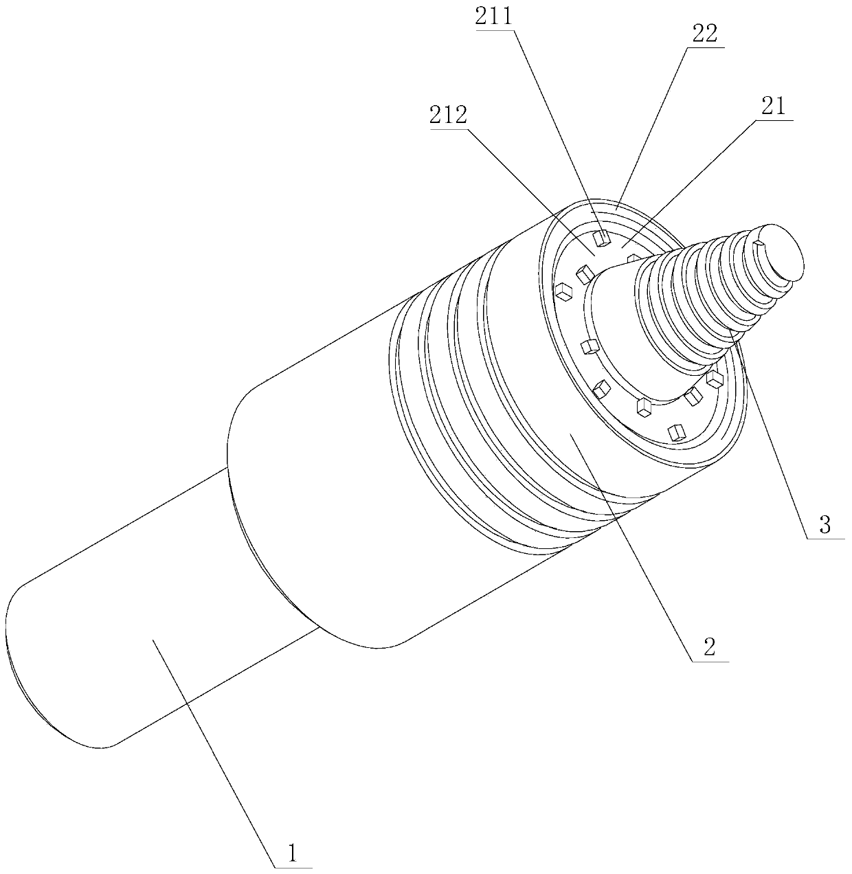
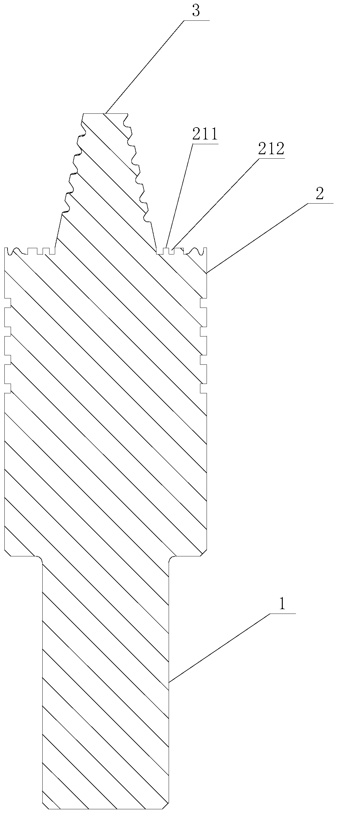
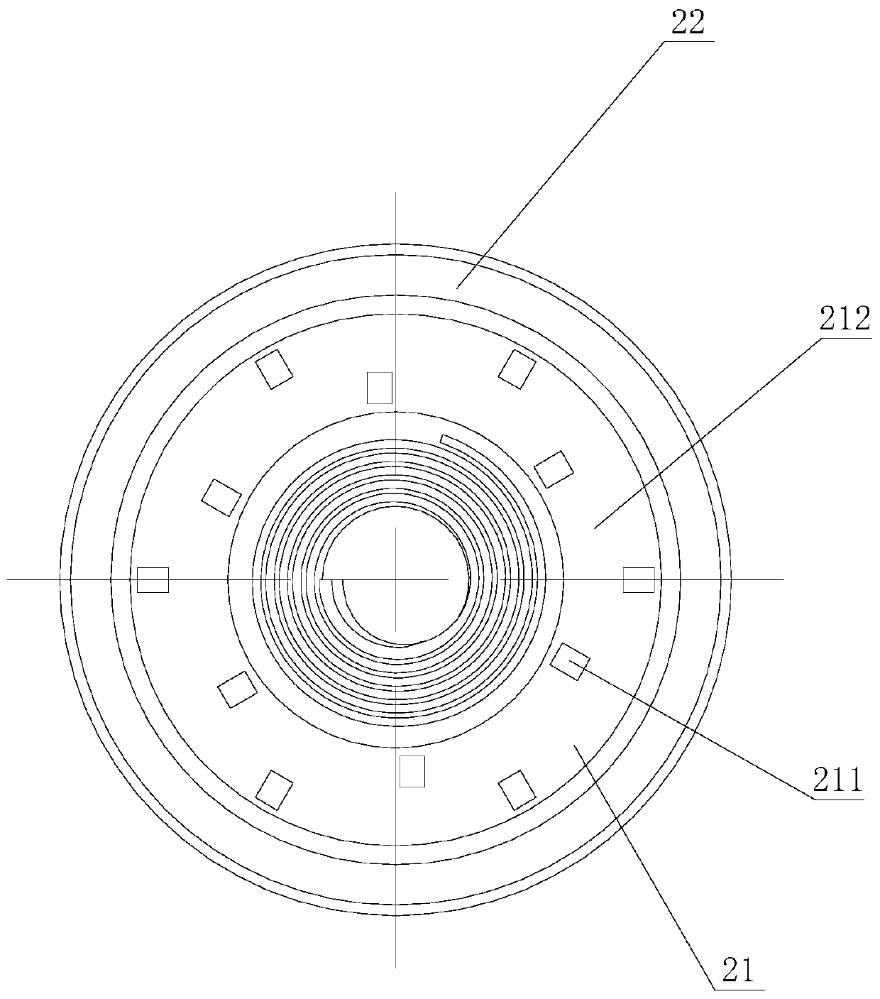
[0029] Such as Figure 1 to Figure 3 As shown, the first embodiment of the stirring head used in the friction stir welding of the present invention has a depth-changing stirring head, including a clamping part 1, a shaft shoulder part 2 and a stirring needle 3 connected in sequence, and the end surface of the shaft shoulder part 2 Including the enveloping area 22 away from the stirring needle 3 in the radial direction, the end surface of the shoulder 2 also includes a stirring area 21 for increasing the frictional moment and having a depth change at least in the circumferential direction, the stirring area 21 is in the radial direction close to the stirring needle 3. In this structure, the enveloping area 22 is set as a gentle surface, which is beneficial to wrapping and forging plastic metal; and the stirring area 21 has a depth-changing structure at least in the circumferential direction, and the depth-changing structure can effectively improve the friction when the stirring...

Embodiment 2

[0033] Such as Figure 4 to Figure 6 As shown, the stirring zone of the present invention for friction stir welding has a second embodiment of a stirring head with varying depths. The groove 212 forms a depth change in the circumferential direction of the stirring zone 21 . The depth change structure in the circumferential direction increases the stirring force in the circumferential direction.

[0034] In this embodiment, the protrusion 211 is not higher than the envelope area 22 in the axial direction. Its structure is simple and reliable.

Embodiment 3

[0036] Such as Figure 7 to Figure 9 As shown, the stirring zone of the present invention for friction stir welding has a third embodiment of a stirring head with varying depths. The direction is higher than the envelope area 22. Its structure is simple and reliable.


PUM


Abstract

The invention discloses a stirring head with depth variation for a stirring area of friction stir welding. The stirring head comprises a clamping part, a shaft shoulder part and a stirring pin in sequential connection, wherein the end face of the shaft shoulder part comprises an enveloping area far away from the stirring pin in the radial direction and further comprises the stirring area; and thestirring area is used for enlarging the friction moment, has depth variation at least in the circumferential direction and is close to the stirring pin in the radial direction. The stirring head has the advantages of improving the stirring and heat generating effect, avoiding a welding defect and enlarging the stirring force.

Description

technical field [0001] The invention mainly relates to the friction stir welding technology, in particular to a stirring head with varying depths in the stirring zone used for the friction stir welding. Background technique [0002] Friction stir welding is a high-speed rotating stirring head pierced into the workpiece and then moves along the welding direction. Frictional heat is generated at the contact part between the stirring head and the workpiece, so that the surrounding metal forms a plastic softening layer, and the softened layer metal is filled under the action of the stirring head rotation. The cavity formed behind the stirring needle, and the solid phase welding method of material connection is realized under the stirring and extrusion action of the stirring head shaft shoulder and the stirring needle. [0003] The stirring head is composed of a shaft shoulder, a stirring needle and a clamping area. Among them, the function of the shoulder is to apply pressure o...

Claims


Application Information

Patent Timeline
IPC IPC(8): B23K20/12
CPCB23K20/12B23K20/122B23K20/1245B23K20/1255
Inventor 汤雨竹李志明李贤清钟南周长兴
Owner HUNAN JOINFRONT WELDING TECH
Learn More