An automatic loading and unloading device for motor rotor shaft processing

A technology of motor rotor shaft and automatic feeding, applied in metal processing, metal processing equipment, manufacturing tools, etc., can solve the problems of low input cost of manipulator, difficult to guarantee clamping force, high maintenance cost and high input cost

Active Publication Date: 2021-06-04
ANHUI KECHUANG NEWENERGY TECH CO LTD
View PDF9 Cites 0 Cited by
  • Summary
  • Abstract
  • Description
  • Claims
  • Application Information

AI Technical Summary

Problems solved by technology

[0002] During the production process of the motor rotor shaft, it needs to be turned, milled and polished in sections. During this process, the motor rotor shaft needs to be transported to different processing equipment areas. The traditional motor rotor shaft is transported by a manipulator, and the general jaw clamp of the manipulator The holding force needs to be adjusted repeatedly to achieve absolute stable accuracy; but generally there will be multiple step distances on the motor rotor shaft, which will affect the clamping effect. More importantly, the length and diameter of the motor rotor shaft will have different changes. It is difficult to guarantee the clamping strength; in addition, if the conveying volume is too large, multiple manipulators need to cooperate with each other, but the input cost of manipulators is not low, too many will lead to high maintenance costs and input costs

Method used


Image

  • An automatic loading and unloading device for motor rotor shaft processing
  • An automatic loading and unloading device for motor rotor shaft processing
  • An automatic loading and unloading device for motor rotor shaft processing

Examples


Embodiment Construction

[0030] The technical solutions of the present invention will be further described below in conjunction with the accompanying drawings and through specific implementation methods.

[0031] Wherein, the accompanying drawings are only for illustrative purposes, showing only schematic diagrams, rather than physical drawings, and should not be construed as limitations on this patent; in order to better illustrate the embodiments of the present invention, some parts of the accompanying drawings will be omitted, Enlargement or reduction does not represent the size of the actual product; for those skilled in the art, it is understandable that certain known structures and their descriptions in the drawings may be omitted.

[0032] In the drawings of the embodiments of the present invention, the same or similar symbols correspond to the same or similar components; , "inner", "outer" and other indicated orientations or positional relationships are based on the orientations or positional ...


PUM


Abstract

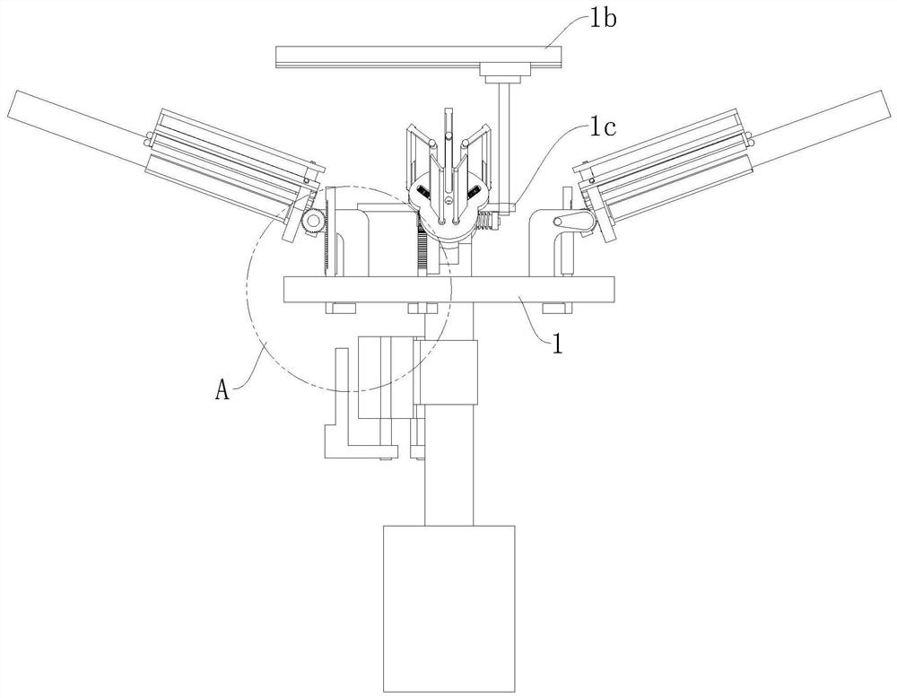
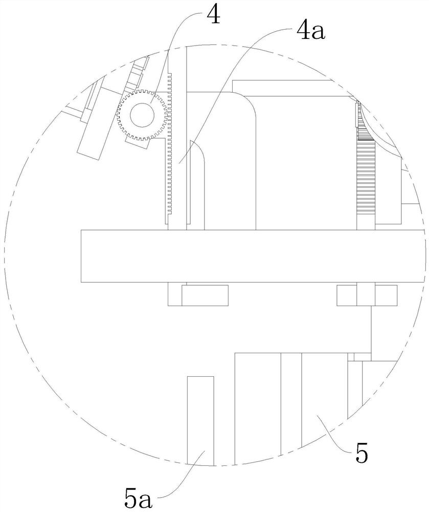
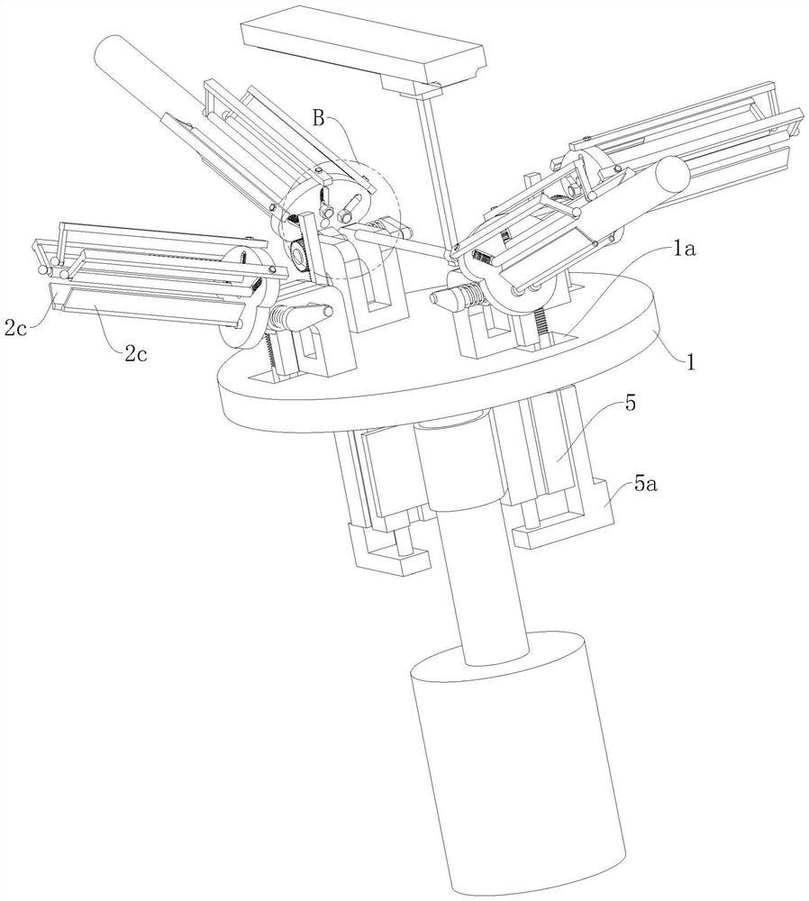
The invention relates to the technical field of motor rotor shaft processing, in particular to an automatic loading and unloading device for motor rotor shaft processing, including a step-type transfer table, a discharge electric cylinder and four supporting parts, and a step-type transfer table The top is provided with four fixed seats distributed at equal angles around the circumference. All the supporting parts are respectively installed on a fixed seat. One end of the supporting part is connected to the fixed seat through the first positioning shaft. The first positioning shaft One end is provided with a positioning torsion spring, and the other end is provided with a transmission structure. The positioning torsion spring is used to limit the upward tilt of the supporting part under normal conditions. The supporting part is provided with a positioning part. There are two adjustment parts, and each adjustment part can correspond to all the supporting parts one by one. The adjustment part can be connected with the transmission structure and used to drive the first positioning shaft to rotate counterclockwise. The utility model has a simple and clear structure and can It is suitable for the transfer and conveying work of motor rotor shafts of different lengths and diameters.

Description

technical field [0001] The invention relates to the technical field of motor rotor shaft processing, in particular to an automatic loading and unloading device for motor rotor shaft processing. Background technique [0002] During the production process of the motor rotor shaft, it needs to be turned, milled and polished in sections. During this process, the motor rotor shaft needs to be transported to different processing equipment areas. The traditional motor rotor shaft is transported by a manipulator, and the general jaw clamp of the manipulator The holding force needs to be adjusted repeatedly to achieve absolute stable accuracy; but generally there will be multiple step distances on the motor rotor shaft, which will affect the clamping effect. More importantly, the length and diameter of the motor rotor shaft will have different changes. It is difficult to guarantee the clamping strength; in addition, if the conveying volume is too large, the mutual cooperation of mult...

Claims


Application Information

Patent Timeline
Patent Type & Authority Patents(China)
IPC IPC(8): B24B41/00B23Q7/04B23Q7/00
CPCB23Q7/00B23Q7/04B24B41/005
Inventor 徐尼云
Owner ANHUI KECHUANG NEWENERGY TECH CO LTD
Why Eureka
Try Eureka