Cam gluing control mechanism applied to paper bag machine

A technology of control mechanism and paper bag machine, which is applied in the direction of papermaking, bag making, paper/cardboard containers, etc. It can solve the problems of difficulty in tearing off, affecting the packaging process of paper bags, and low sealing efficiency of paper bags, so as to simplify the control structure and prevent The effect of production error and precision guarantee

Pending Publication Date: 2020-03-27
黄胜福
View PDF0 Cites 0 Cited by
  • Summary
  • Abstract
  • Description
  • Claims
  • Application Information

AI Technical Summary

Problems solved by technology

[0002] At present, paper bags are widely used in the packaging field. Before the paper bag is formed, it is a blank sheet of paper. The paper sheet is produced into a paper bag by a paper bag machine. The paper bag machine can process the paper on the paper tube through edge correction, breaking, folding, After the breaking and edge sealing process, the finished paper bag is formed and output in stacks. After the paper bag is manufactured, one end of the paper bag is sealed, while the other end is open. After the items are loaded from the open end of the paper bag, the opening The existing post-sealing process includes double-sided adhesive sealing, glue sealing and other packaging processes, and the above-mentioned double-sided adhesive sealing needs to be torn off the sticker, and then folded and pasted to seal, but the double-sided adhesive The action of tearing off the sticker needs to be done manually. At the same time, it is difficult to realize the tearing action according to the existing manipulator technology, resulting in extremely low sealing efficiency of the paper bag, which cannot meet the current post-sealing process requirements and affects the entire packaging process of the paper bag. The hot-melt adhesive seal in the glue seal can solve the problem that the above-mentioned process cannot be carried out by automatic equipment. It only needs to pre-coat the hot-melt adhesive on the surface of the long paper bag. The hot-melt a

Method used


Image

  • Cam gluing control mechanism applied to paper bag machine
  • Cam gluing control mechanism applied to paper bag machine
  • Cam gluing control mechanism applied to paper bag machine

Examples


Embodiment

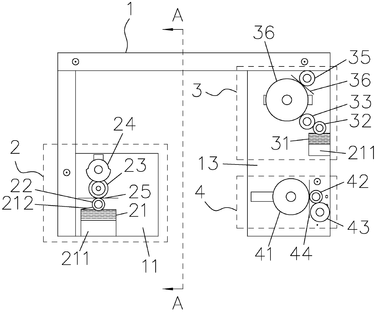
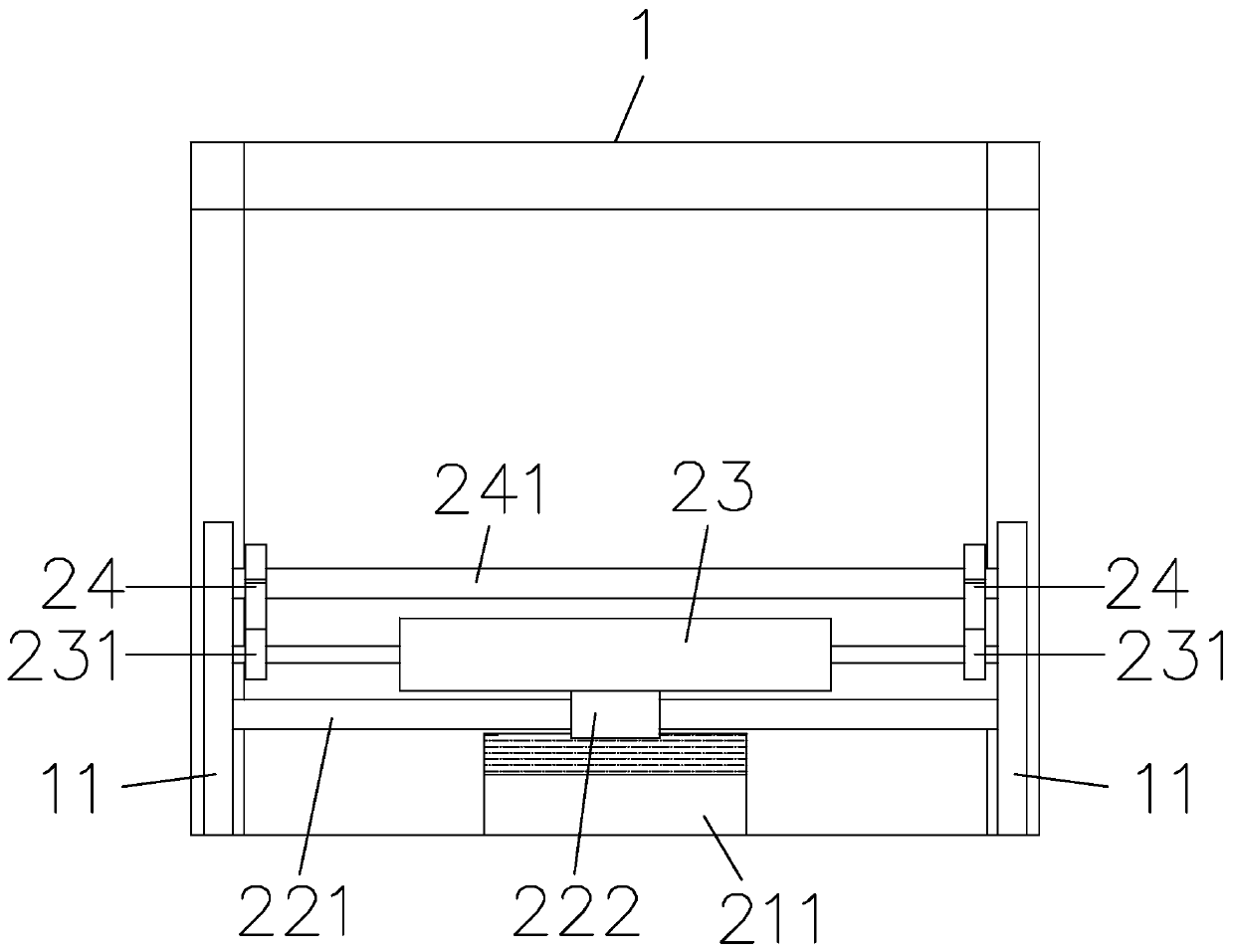
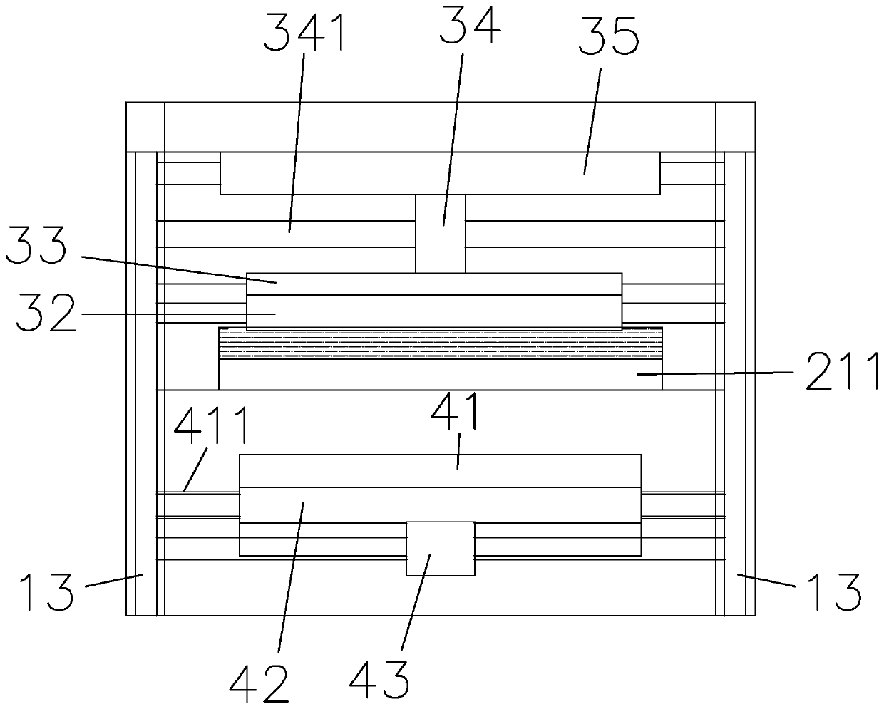
[0026] Such as Figure 1 to Figure 4 As shown, this embodiment discloses a cam gluing control mechanism applied to a paper bag machine, including a frame 1, a gluing mechanism 2 installed at one end of the frame 1, a printing mechanism 3 installed at the other end of the frame 1 and Cutting mechanism 4, described gluing mechanism 2 comprises glue box 21, is arranged on glue roller 22 above glue box 21, is arranged on the glue printing auxiliary roller 23 above glue roller 22, is arranged on the cam above glue roller 24. The rubber printing auxiliary roller 23 moves up and down with the rotation of the cam 24, and alternately separates and sticks with the upper rubber roller 22. Glue channel 25; described printing mechanism 3 comprises ink tank 31, the ink wheel 32 that is arranged on ink tank 31 tops, the screen printing wheel 33 that is arranged on ink wheel 32 tops, the resin plate printing wheel 34 that is arranged on screen printing wheel 33 tops , the guide wheel 35 that...


PUM


Abstract

The invention discloses a cam gluing control mechanism applied to a paper bag machine, which comprises a frame, a gluing mechanism mounted at one end of the frame, and a printing mechanism and a markcutting mechanism mounted at the other end of the frame; by the synchronous transmission among the gluing mechanism, the printing mechanism and the mark cutting mechanism, the gluing, printing and mark cutting process of paper bags are synchronized at corresponding stations, thereby effectively preventing production errors of the paper bags due to transmission on a production line, and ensuring the accuracy of paper bag production; and at the same time, through the synchronous transmission of the mechanisms, no complex control system is needed to perform synchronous control on the three processes when surface gluing, printing and mark cutting processes are performed on the paper bags, as a result, the control structure is simplified, the manufacturing cost of the paper bag machine is reduced, and the production of the paper bags is stabilized.

Description

technical field [0001] The invention relates to the technical field of paper bag machines, in particular to a cam gluing control mechanism applied to paper bag machines. Background technique [0002] At present, paper bags are widely used in the packaging field. Before the paper bag is formed, it is a blank sheet of paper. The paper sheet is produced into a paper bag by a paper bag machine. The paper bag machine can process the paper on the paper tube through edge correction, breaking, folding, After the breaking and edge sealing process, the finished paper bag is formed and output in stacks. After the paper bag is manufactured, one end of the paper bag is sealed, while the other end is open. After the items are loaded from the open end of the paper bag, the opening The existing post-sealing process includes double-sided adhesive sealing, glue sealing and other packaging processes, and the above-mentioned double-sided adhesive sealing needs to be torn off the sticker, and th...

Claims


Application Information

Patent Timeline
IPC IPC(8): B31B70/62B31B70/88B31B70/00B31B70/74
CPCB31B70/25B31B70/62B31B70/74B31B70/88
Inventor 黄胜福
Owner 黄胜福
Why Eureka
Try Eureka