
Vibrating feeder

A vibrating feeder and feeding trough technology, which is applied in the field of feeding and feeding, can solve problems such as affecting the quality of aggregates, unfavorable energy saving, plugging and accumulating materials, etc. Vibration strong effect

Pending Publication Date: 2020-03-27
BCEG RESOURCES RECYCLING CO LTD
View PDF0 Cites 2 Cited by
  • Summary
  • Abstract
  • Description
  • Claims
  • Application Information

AI Technical Summary

Problems solved by technology

For example, when the construction waste contains a lot of soil and fine powder, or when the humidity of the construction waste is high, the soil content of the recycled aggregate obtained after disposal will often increase, which will affect the quality of the aggregate; at the same time, if the disposal line There is always a lot of soil mixed in, which not only affects the production capacity of the equipment, but also is not conducive to energy saving
In view of this, the vast majority of construction waste disposal enterprises currently adopt a certain soil removal device when the construction waste is fed or at the front end of the disposal process line to remove fine materials or soil in the construction waste, and use a vibration machine with a certain sieve hole. It is a relatively common method for the feeder to remove soil during the feeding process, but the existing vibrating feeder generally feeds through a single-layer receiving panel, in order to prevent the crushed aggregate particles in the feeding For soil treatment, the openings on the receiving panel are usually small, generally 10-30mm, but such opening size will make the openings on the feeding panel larger when the soil content in the feeding material is large or the humidity of the feeding material is high. The holes are often blocked. After the holes are blocked, a large amount of soil and fine powder will enter the subsequent disposal process, even in the aggregate product, affecting the quality of the aggregate.
The existing vibrating feeder with sieve holes also has two layers of screen surface, the upper layer is a thicker material receiving panel with holes, and the lower layer is an ordinary flat woven screen. Compared with the former, the openings are larger, so the material blocking on the receiving panel is less, but when the lower layer of woven mesh encounters the situation of large soil content and high humidity in the feeding material, it is also prone to blockage The phenomenon of porosity

Method used


Image

  • Vibrating feeder

Examples


Embodiment Construction

[0020] The following will clearly and completely describe the technical solutions in the embodiments of the present invention with reference to the accompanying drawings in the embodiments of the present invention. Obviously, the described embodiments are only some, not all, embodiments of the present invention. Based on the embodiments of the present invention, all other embodiments obtained by persons of ordinary skill in the art without making creative efforts belong to the protection scope of the present invention.

[0021] The purpose of the present invention is to provide a vibrating feeder to solve the problems in the prior art, so that the screen of the vibrating feeder is not easy to be blocked and the soil removal effect is enhanced.

[0022] In order to make the above objects, features and advantages of the present invention more comprehensible, the present invention will be further described in detail below in conjunction with the accompanying drawings and specific ...


PUM


Abstract

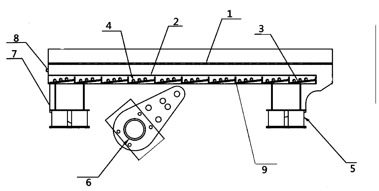
The invention discloses a vibrating feeder, which relates to the technical field of feeding and conveying in construction waste disposal. The vibrating feeder comprises two side plates, a material receiving panel, a composite sieve plate, a vibration excitation device and a vibration reduction device, wherein the side plates, the material receiving panel and the composite sieve plate form a firstfeeding groove body and a second feeding groove body, a bottom plate of the first feeding groove body is the material receiving panel and directly receives feeding of an excavator or a forklift, a bottom plate of the second feeding groove body is the composite sieve plate, the vibration excitation device provides a vibration excitation force, and the vibration excitation force is used for drivingmaterials to move toward a material outlet; the composite sieve plate comprises an upper sieve plate, a lower sieve plate and a plurality of bouncing balls between the upper and lower sieve plates; the upper sieve plate of the composite sieve plate is parallel to the bottom plate of the first feeding groove, the lower sieve plate is composed of a plurality of sections of inclined sieve plates, partition plates between every two sections of adjacent inclined sieve plates, a front end partition plate and a rear end partition plate; the partition plates, the front end partition plate and the rearend partition plate are fixed to side plates of the vibrating feeder, and the inclined sieve plates are fixed to the two partition plates. The sieves of the vibrating feeder provided by the inventionare not prone to blockage, and the soil removal effect is enhanced.

Description

technical field [0001] The invention relates to the technical field of feeding and feeding, in particular to a vibrating feeder. Background technique [0002] At present, the effective consumption and recycling of construction waste has become the focus of the whole society. However, due to the huge volume of construction waste, the composition of construction waste from different sources in different regions usually fluctuates greatly. In addition to aggregate components such as concrete, soil Soil is also a common component of construction waste, and its content is usually 5%-40%, and some construction waste with high soil content can contain more than 70%. When disposing of construction waste, the soil content of the construction waste input material and the humidity of the soil fine powder have a great influence on the effect of process disposal. For example, when the construction waste contains a lot of soil and fine powder, or when the humidity of the construction was...

Claims


Application Information

Patent Timeline
Patent Type & Authority Applications(China)
IPC IPC(8): B65G27/00B65G27/18B07B1/28
CPCB65G27/00B65G27/18B07B1/28
Inventor 李烁狄永浩张洪杰袁振航赵国锋魏中明
Owner BCEG RESOURCES RECYCLING CO LTD
Learn More