
Efficient dyeing equipment for textile cloth

A kind of dyeing equipment and high-efficiency technology, which is applied in the direction of processing textile material equipment configuration, textiles and papermaking, textile processing machine accessories, etc., can solve the problems of general stirring effect, tearing and damage of cloth, and slow dyeing speed, so as to improve the dyeing effect, The effect of preventing cloth damage and avoiding the use of stirring rods

Inactive Publication Date: 2020-03-27
安徽云至信电子商务有限公司
View PDF0 Cites 8 Cited by
  • Summary
  • Abstract
  • Description
  • Claims
  • Application Information

AI Technical Summary

Problems solved by technology

[0009] However, the dyeing speed of this method is slow, and at the same time, the dyeing is prone to unevenness and the consumption of dyes is large.
There have also been some mechanical dyeing devices, but for the sake of uniformity of these devices, most of these dyeing devices use a motor-driven stirring rod to stir the dye, but the stirring area is fixed and the stirring effect is general; in addition, the stirring rod If it comes into contact with the cloth, it is easy to cause the cloth to tear and be damaged

Method used


Image

  • Efficient dyeing equipment for textile cloth
  • Efficient dyeing equipment for textile cloth
  • Efficient dyeing equipment for textile cloth

Examples


Embodiment 1

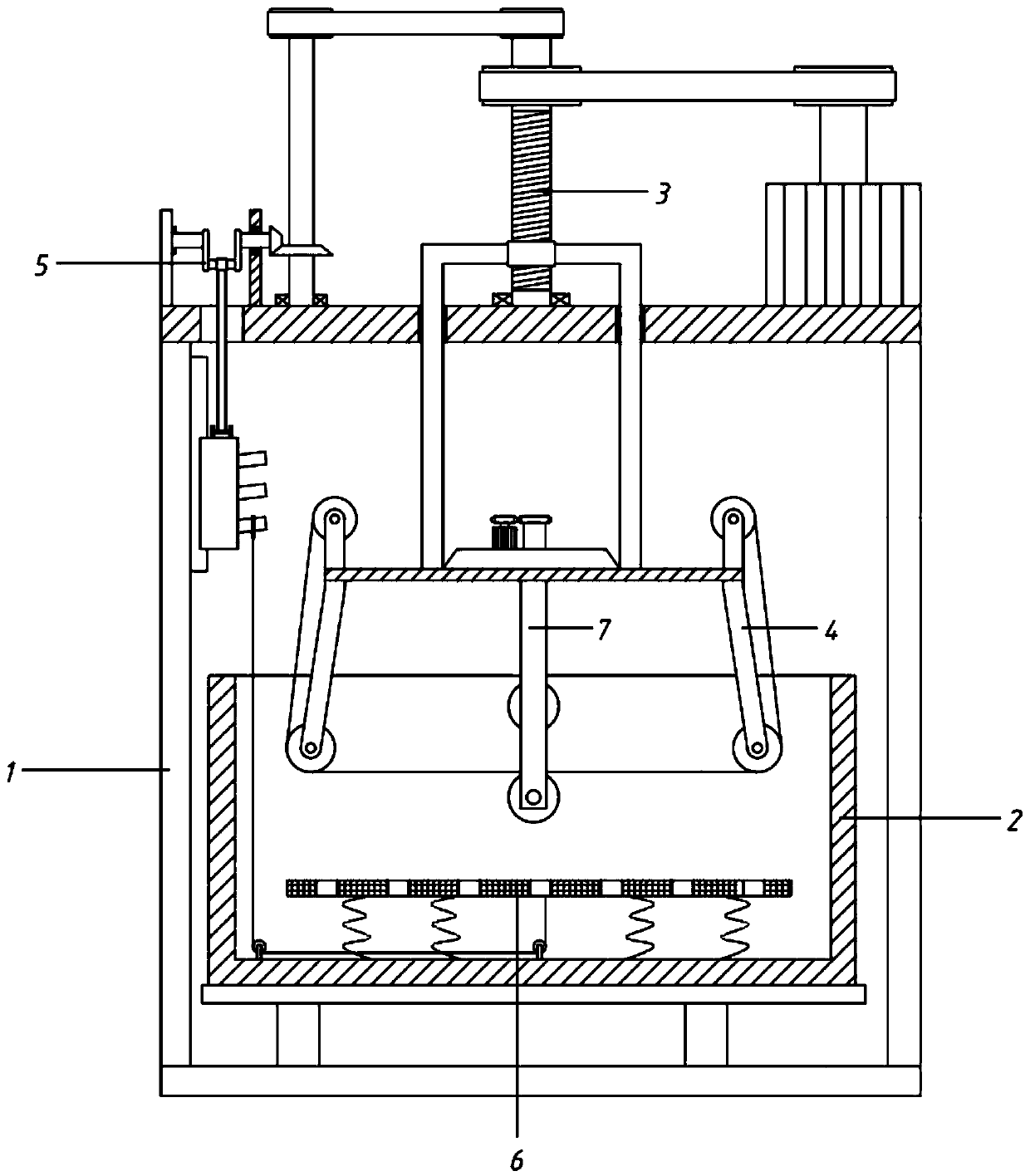
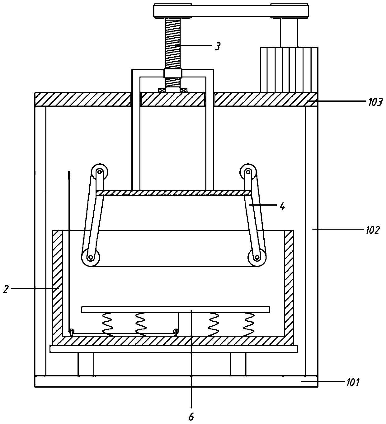
[0059] A high-efficiency dyeing equipment for textile cloth, including a frame 1, a dyeing box 2, a lifting component 3, a dyeing component 4 and a turbulent flow component 6;

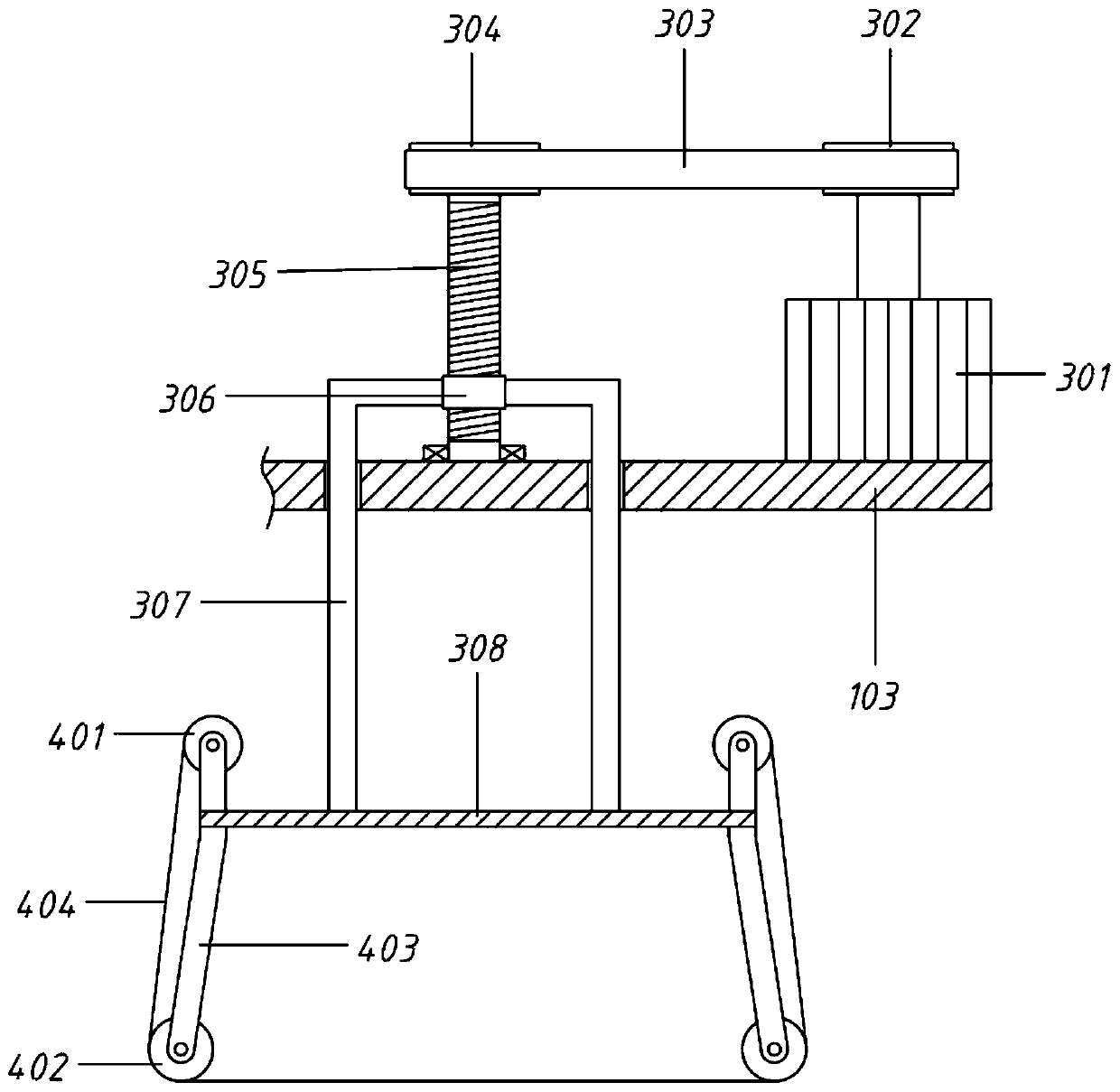
[0060] The frame 1 includes a bottom plate 101, a vertical plate 102 and a top plate 103, the vertical plate 102 is fixedly connected to the left and right ends of the bottom plate 101, and the top of the vertical plate 102 is connected by the top plate 103; the dyeing box 2 is arranged above the bottom plate 101; Component 6; the lifting component 3 is arranged on the top plate 103, and the lifting component 3 passes through the top plate 103 downwards and is connected with the dyeing component 4.

Embodiment 2

[0062] A high-efficiency dyeing equipment for textile cloth, including a frame 1, a dyeing box 2, a lifting component 3, a dyeing component 4 and a turbulent flow component 6;

[0063] The frame 1 includes a bottom plate 101, a vertical plate 102 and a top plate 103, the vertical plate 102 is fixedly connected to the left and right ends of the bottom plate 101, and the top of the vertical plate 102 is connected by the top plate 103; the dyeing box 2 is arranged above the bottom plate 101; Component 6; the lifting component 3 is arranged on the top plate 103, and the lifting component 3 passes through the top plate 103 downwards and is connected with the dyeing component 4.

[0064] Wherein, the dyeing box 2 includes a box body 203, a placement plate 202 and a pole 201, the placement plate 202 is fixedly connected above the base 101 by the pole 201, the box body 203 is placed on the placement plate 202, and the top of the box body 203 is provided with an opening. It is convenie...

Embodiment 3

[0076] On the basis of embodiment 2,

[0077] The retractable structure 401 includes the retractable roller 4011, the mounting end 4012, the mounting base 4013, the first type of support plate 4014, the second servo motor 4015, the moving block 4016, the first slide rail 4017, the second type of support plate 4018, and the second screw 4019 and handle 4020;

[0078] The first-class support plates 4014 are symmetrically arranged front and back, and the bottom of one of the first-class support plates 4014 is connected with a moving block 4016, and the bottom of the moving block 4016 is slidably connected to a No. 1 slide rail 4017, and the No. The two ends of the rail 4017 are provided with a class of support plates 4018, and a No. 2 screw 4019 is rotated between the Class 4 support plates 4018. The No. 2 screw 4019 passes through and is screwed to the moving block 4016. One end of the No. 2 screw 4019 is externally connected with a handle 4020; The opposite side of the class s...


PUM


Abstract

The invention relates to the technical field of cloth dyeing equipment, in particular to efficient dyeing equipment for textile cloth. By means of a mode of tightening a pull rope and then loosening the pull rope, a turbulence plate moves up and down under the action of the pull rope and a spring, so that turbulence is generated on dye in a box body, and the dye is more uniform; meanwhile, the uniform mixing mode of the dye is adopted, and use of a stirring rod is avoided, so that the situation that the cloth is damaged caused by contact between the cloth and the stirring rod is avoided; and afirst servo motor is adopted to drive a first screw rod to rotate through a transmission belt, and the first screw rod rotates forwards and reversely. A threaded sleeve suffers from a threaded actionand is also guided by 7-shaped rods on the two sides, and finally moves axially along the first screw rod, so that a mounting plate is driven to move up and down, the position of a dyeing assembly isadjusted, and the cloth is immersed in the dye conveniently; and the mounting plate can move up and down in a reciprocating mode by adjusting the first servo motor and controlling the first servo motor to perform small-amplitude forward and backward rotation, the cloth is shaken, more dyes are adsorbed, and the dyeing effect is improved.

Description

technical field [0001] The invention relates to the technical field of cloth dyeing equipment, in particular to a high-efficiency dyeing equipment for textile cloth. Background technique [0002] Textile cloth, that is, cloth, is a general term for all kinds of fabrics. [0003] In terms of raw materials, it can be divided into cotton cloth, chemical fiber cloth, linen cloth, woolen cloth, silk and so on. [0004] Cotton cloth has good hygroscopicity and air permeability, soft and comfortable to wear, good warmth retention, good wearing performance, good dyeing performance, bright color, complete color spectrum, strong alkali resistance, heat and light resistance; but poor acid resistance, poor elasticity, shrinkage rate Large, easy to wrinkle, easy to mold, if exposed to sunlight for a long time, the strength will be reduced, the fiber will become hard and brittle, but it is resistant to insects, it is an ideal underwear material, and it is also a high-quality and cheap pu...

Claims


Application Information

Patent Timeline
IPC IPC(8): D06B3/10D06B23/04D06B23/20D06B15/02
CPCD06B3/10D06B15/02D06B23/04D06B23/205
Inventor 万燕
Owner 安徽云至信电子商务有限公司
Learn More