Novel landslip-resistant shed tunnel and construction method

A shed cave, a new type of technology, applied in excavation, infrastructure engineering, construction, etc., can solve the problem that the shed cave does not have the ability to resist lateral slippage, so as to increase the ability to resist lateral deformation, improve stability, and improve The effect of structural stability

Pending Publication Date: 2020-03-27
四川省交通勘察设计研究院有限公司
View PDF0 Cites 0 Cited by
  • Summary
  • Abstract
  • Description
  • Claims
  • Application Information

AI Technical Summary

Problems solved by technology

[0004] The purpose of the present invention is to provide a new type of shed cave that can resist landslides, has a strong ability to resist lateral deformation, and solves the problem that the existing shed cave does not have the ability to resist lateral sliding

Method used


Image

  • Novel landslip-resistant shed tunnel and construction method
  • Novel landslip-resistant shed tunnel and construction method

Examples


Embodiment 1

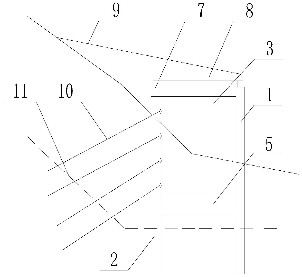
[0042] Such as figure 1 , figure 2 As shown, a new type of shed cave that can resist landslides, including 4 face piles 1 arranged in rows and 4 back piles 2 arranged in rows, the cylindrical structure of the average radius of 1m of the face piles 1 and back piles 2, The distance between the adjacent face piles 1 and the adjacent back piles 2 is 6m to 8m, the back piles 2 are arranged on one side close to the mountain body, the face piles 1 are arranged on the other side, and the adjacent face piles 1 or the tops of adjacent back piles 2 are connected by top longitudinal beams 4, and the lower parts of adjacent surface piles 1 or adjacent back piles 2 are connected by bottom longitudinal beams 6, and the surface piles 1 and back piles 2 The tops of the tops are connected by top transverse beams 3, the bottom of the surface pile 1 and the back pile 2 are connected by a bottom beam 5, the bottom longitudinal beam 6 and the bottom beam 5 are arranged at the same height, and the...

Embodiment 2

[0044] Such as figure 1 , figure 2 As shown, this embodiment is based on Embodiment 1, the face pile 1 is 0.5m to 1m higher than the back pile 2, the top of the top transverse tie beam 3 is flush with the top of the back pile 2, and is arranged on the face pile The support 7 on one side is 0.5m to 1m shorter than the support 7 on one side of the back pile 2 .

[0045] A construction method of a novel shed cave that can resist landslides as described in any one of embodiment 1 or embodiment 2, comprising the following steps:

[0046] 1) The surface pile 1 and the back pile 2 are respectively prepared by using the concrete pouring process: the back pile 2 and the surface pile 1 are inserted into the unstable soil body 10 in a row until the bottom is inserted into the embedded section stratum;

[0047] 2), using the concrete pouring process to prepare the top longitudinal beam 4 and the top transverse beam 3 respectively;

[0048] 3), when the top longitudinal beam 4 and the ...


PUM


Abstract

The invention discloses a novel landslip-resistant shed tunnel and a construction method. The novel landslip-resistant shed tunnel includes a plurality of face piles arranged in rows and a plurality of back piles arranged in rows. The back piles are arranged on the side near a mountain, the face piles are arranged on the other side, the tops of adjacent face piles or adjacent back piles are connected through top longitudinal beams, and the lower parts of adjacent face piles or adjacent back piles are connected through bottom longitudinal beams. The tops of the face piles and the back piles areconnected through top transverse beam, the lower parts of the face piles and the back piles are connected through bottom transverse beams, and the bottoms of the face piles and the back piles are inserted into embedded-fixed section stratum below a sliding surface. Supporting seats are arranged on the upper end surfaces of the top longitudinal beams, and top plates are arranged at the tops of thesupporting seats. The novel landslip-resistant shed tunnel has a strong ability to resist lateral deformation, and the problem that an existing shed tunnel has no ability to resist lateral slippage is solved.

Description

technical field [0001] The invention relates to the technical field of road traffic safety protection facilities, in particular to a novel shed cave capable of resisting landslides and a construction method. Background technique [0002] In recent years, after many geological disasters such as strong earthquakes and high-level landslides in mountainous areas, the rush to clear and maintain roads in mountainous areas with complex terrain conditions has become a "lifeline" project. Practice has proved that the construction of reinforced concrete sheds is an effective measure to protect against falling rocks under narrow terrain conditions, steep slopes, and high requirements for traffic protection. [0003] However, the structure of the shed tunnel does not have the ability to resist lateral slippage, and it needs to be set in a stable geological environment. When the route passes through landslides or unstable soil, support piles are generally used for protection, but if roc...

Claims


Application Information

Patent Timeline
IPC IPC(8): E02D17/20
CPCE02D17/207
Inventor 袁松王峥峥谢凌志黎良仆
Owner 四川省交通勘察设计研究院有限公司
Why Eureka
Try Eureka