Steel plate interface bolt connecting structure and method for reinforced concrete column and column

A reinforced concrete column and connecting structure technology, which is applied in the direction of building structure and construction, can solve the problems of high grouting technology level, weak connection interface integrity, and high construction alignment requirements, so as to improve the compressive and shearing resistance , Good shear resistance and easy production

Inactive Publication Date: 2020-03-27
CHINA UNIV OF MINING & TECH
View PDF9 Cites 3 Cited by
  • Summary
  • Abstract
  • Description
  • Claims
  • Application Information

AI Technical Summary

Problems solved by technology

[0004] The existing prefabricated reinforced concrete frame structure mainly adopts cast-in-place nodes at the floor position for column-to-column connection, and the prefabricated column members will have exposed steel bars, and formwork and pouring are required for on-site assembly and connection. At the same time, column-to-column The steel bars are connected by sleeve grouting, which requires high construction alignment and high grouting technology level. Therefore, the efficiency of prefabricated assembly is low, and the integrity of the connection interface is weak

Method used


Image

  • Steel plate interface bolt connecting structure and method for reinforced concrete column and column
  • Steel plate interface bolt connecting structure and method for reinforced concrete column and column
  • Steel plate interface bolt connecting structure and method for reinforced concrete column and column

Examples


Embodiment Construction

[0039] The present invention will be further described below in conjunction with the accompanying drawings.

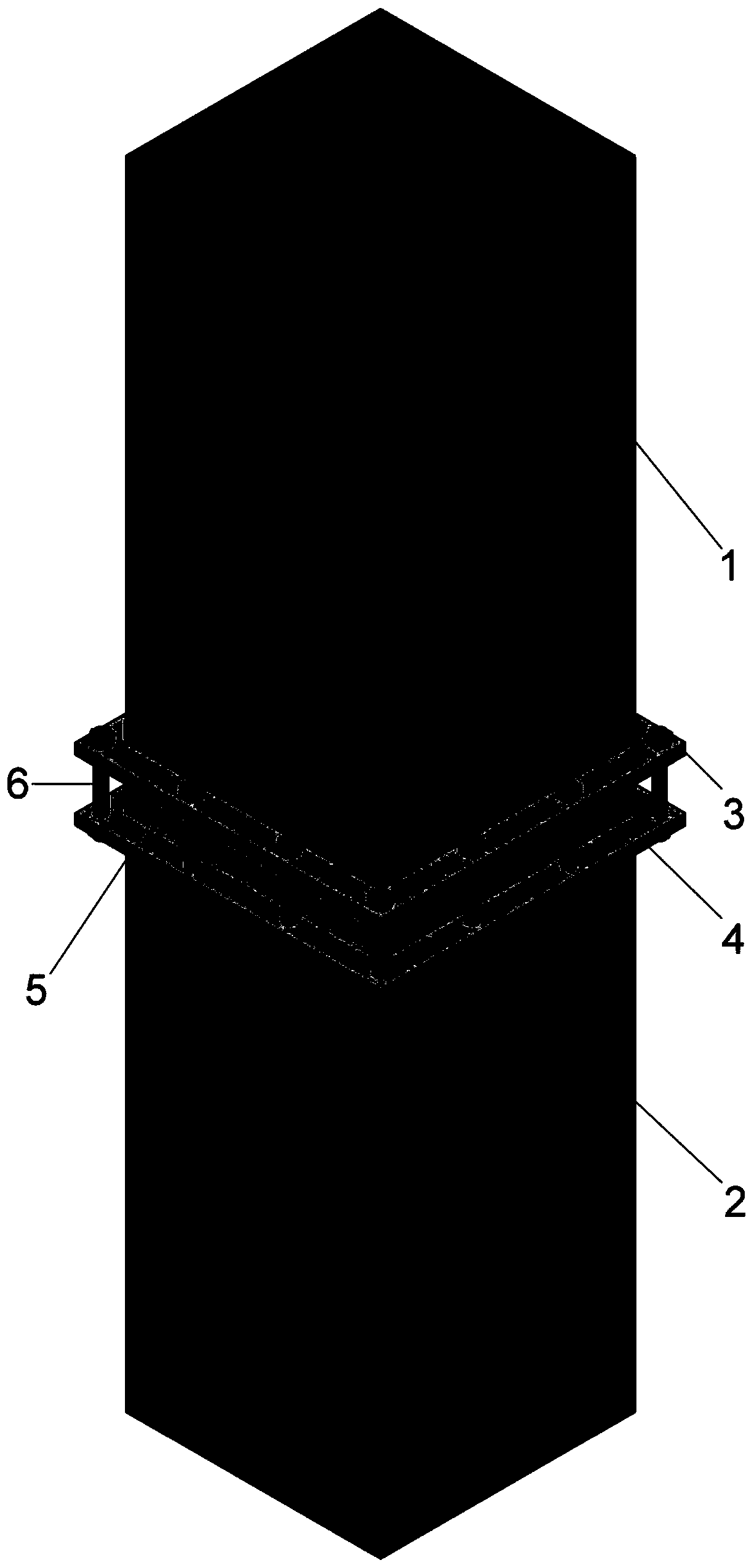
[0040] Such as Figure 1~4 Shown is a reinforced concrete column-to-column steel plate interface bolt connection structure, through the auxiliary upper column steel plate assembly 3, lower column steel plate assembly 4, interlayer assembly 5 and connecting bolts 6 to realize the connection of prefabricated upper column 1 and lower column 2 .

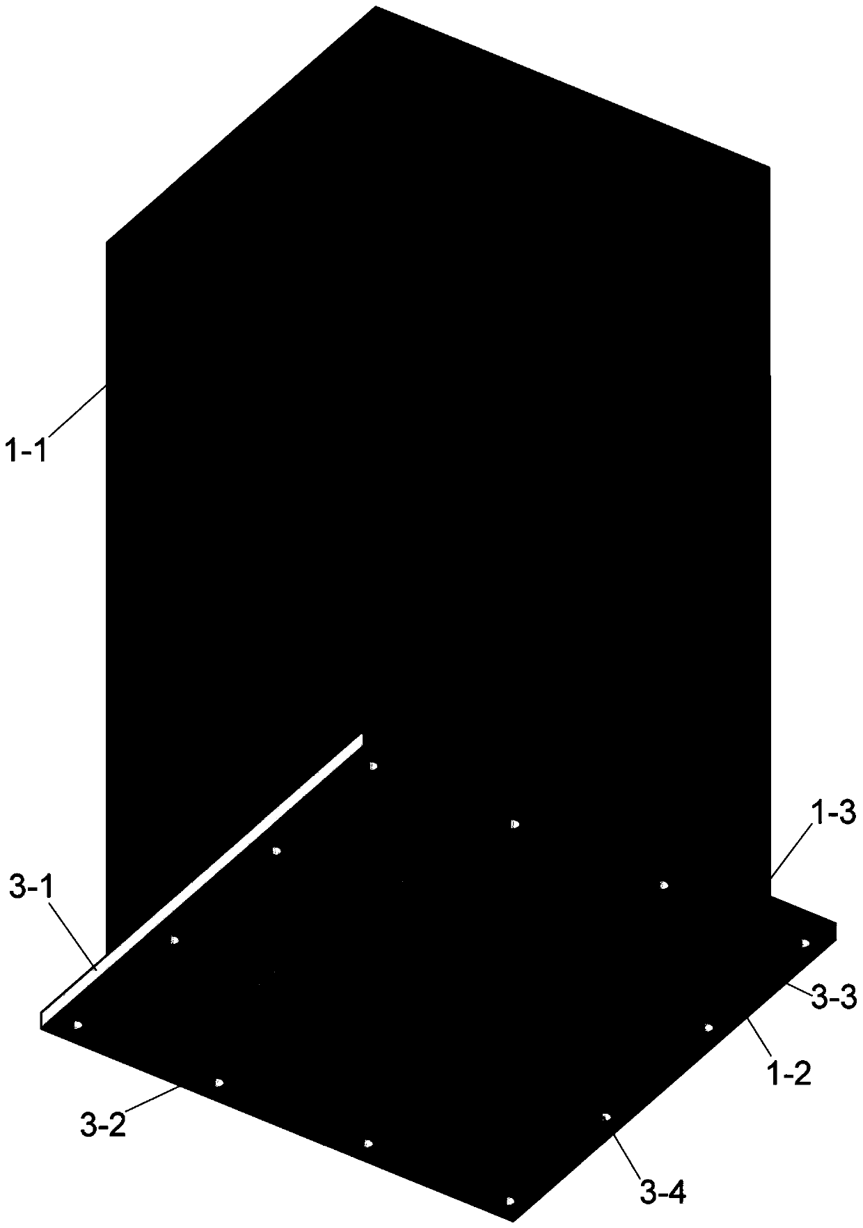
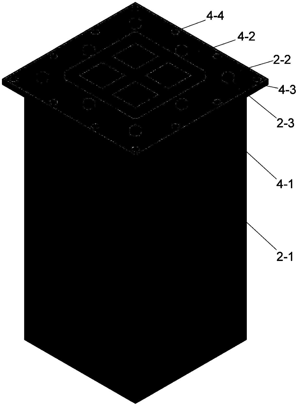
[0041] The upper column 1 and the lower column 2, the main body is a reinforced concrete prefabricated column with a conventional rectangular section, no reinforcement, no holes; the upper column 1 is composed of upper column concrete 1-1, upper column longitudinal reinforcement 1-2, upper column The column nut 1-3 is composed, and the lower column 2 is composed of the lower column concrete 2-1, the lower column longitudinal reinforcement 2-2, and the lower column nut 2-3.

[0042] The upper column longitudinal rib 1-2 protrude...


PUM


Abstract

The invention discloses a steel plate interface bolt connecting structure and method for a reinforced concrete column and a column, and the connection of a prefabricated column and a column is realized by using a connecting bolt through an upper column steel plate assembly and a lower column steel plate which are fixed at the column bottom of an upper column and the column top of a lower column and an interlayer assembly clamped between the upper column steel plate assembly and the lower column steel plate. The prefabricated column is in a conventional regular shape, no rib is exposed, and nohole is reserved; the steel plate assemblies of the upper column and the lower column are each composed of an interface steel plate, a set of shear keys, a set of inner ring round holes and a set of outer ring round holes. The interlayer assembly is composed of a steel plate hoop and micro-expansion mortar filled in the steel plate hoop. The connecting method comprises the main steps: manufacturing the steel plate assemblies of the upper column and the lower column, and prefabricating the steel plate assemblies with the upper column and the lower column into a whole; placing the steel plate hoop in place and filling micro-expansion mortar in the steel plate hoop; connecting the upper column interface steel plate and the lower column interface steel plate through connecting bolts, and completing the connection of the upper column and the lower column. The invention provides the connecting structure with more simplified columns and excellent performances.

Description

technical field [0001] The invention relates to a steel plate interface bolt connection structure and connection method between a reinforced concrete column and a column, and is an assembled structure technology in the field of construction engineering. Background technique [0002] In recent years, with the continuous improvement of people's requirements for living conditions and living environment, the construction industry has developed rapidly. However, the development of the construction industry has caused serious resource consumption and environmental pollution, forcing people to seek a new way out of the construction industry. At present, the industrialization of buildings characterized by prefabricated buildings is one of the key ways to achieve low-carbon and sustainable development in the construction industry. [0003] In prefabricated buildings, the connection of structural components has a crucial influence on the efficiency of prefabricated and assembled cons...

Claims


Application Information

Patent Timeline
Patent Type & Authority Applications(China)
IPC IPC(8): E04B1/21
CPCE04B1/215
Inventor 李富民赵婕方渝钰刘昶刘永强丁如瑾李妍颖
Owner CHINA UNIV OF MINING & TECH
Why Eureka
Try Eureka