CEEMD-improved wavelet threshold denoising-based transformer winding ultrasonic detection three-dimensional imaging method

A wavelet threshold denoising, transformer winding technology, used in the re-radiation of sound waves, radio wave measurement systems, and the use of ultrasonic/sonic/infrasonic waves, which can solve the difficulty of threshold function selection, unstable decomposition process, and modal aliasing effects. and other problems, to achieve the effect of easy signal identification, ideal noise reduction performance, and smooth non-faulty areas

Active Publication Date: 2020-03-27
JILIN PROVINCE ELECTRIC POWER RES INST OF JILIN ELECTRIC POWER CO LTD +2
View PDF2 Cites 10 Cited by
  • Summary
  • Abstract
  • Description
  • Claims
  • Application Information

AI Technical Summary

Problems solved by technology

Wavelet transform has great advantages in random noise filtering due to its advantages of multiple decomposition scales and decorrelation, but it has defects such as difficult selection of threshold function and variable number of decomposition layers; Empirical Mode Decomposition (EMD) ) has a strong advantage in non-stationary signal processing, but it is prone to modal aliasing effect, the decomposition process is unstable, the denoising ability is poor, and it is easy to filter out low-amplitude useful information

Method used


Image

  • CEEMD-improved wavelet threshold denoising-based transformer winding ultrasonic detection three-dimensional imaging method
  • CEEMD-improved wavelet threshold denoising-based transformer winding ultrasonic detection three-dimensional imaging method
  • CEEMD-improved wavelet threshold denoising-based transformer winding ultrasonic detection three-dimensional imaging method

Examples


Embodiment Construction

[0069] Include the following steps:

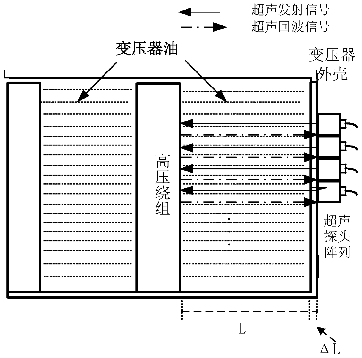
[0070] (1) Ultrasonic detection imaging system

[0071] 1) During ultrasonic testing, the number of ultrasonic array probes can be flexibly adjusted according to needs. Assume that the propagation speed of the ultrasonic wave measured by the nth probe in the transformer oil is a known value v, and the ultrasonic wave is on the surface of the box and the surface of the winding. The time required to travel back and forth between is t, then the distance between the ultrasonic probe and the winding can be calculated as:

[0072]

[0073] In the formula, L is the distance from the ultrasonic probe to the winding surface;

[0074] If the thickness of the steel plate of the transformer box is considered, the formula (1) can be rewritten as

[0075]

[0076] In the formula, △L is the thickness of the steel plate of the transformer box.

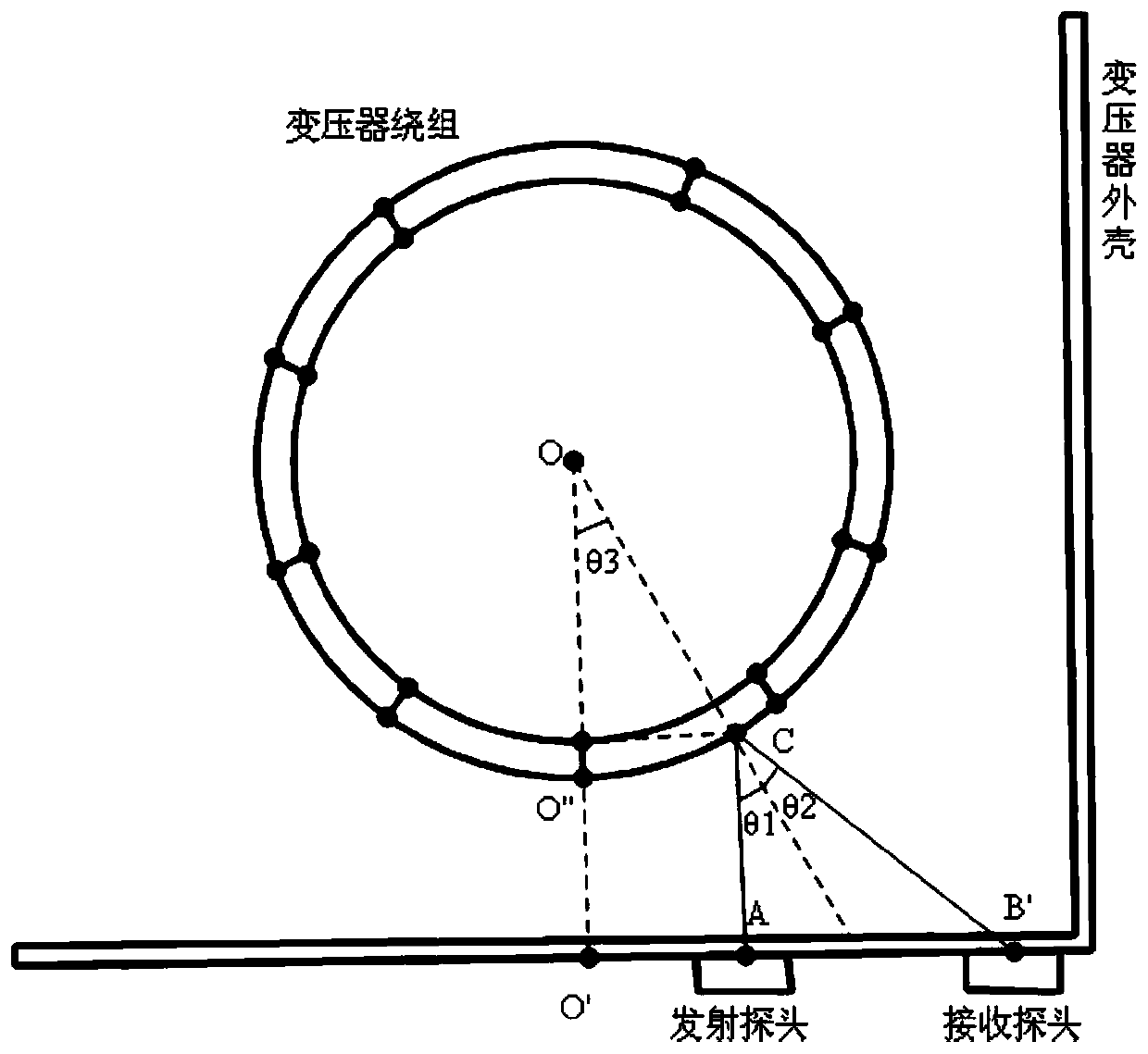
[0077] 2) Ultrasonic distance conversion algorithm

[0078] In order to generate a three-dimensional ...


PUM


Abstract

The invention relates to a CEEMD-improved wavelet threshold denoising-based transformer winding ultrasonic detection three-dimensional imaging method, and belongs to a transformer winding deformationdetection method. The method comprises the following steps: firstly, performing CEEMD decomposition on a target signal to obtain a multi-order IMF component, then calculating a correlation coefficientof the IMF component, performing improved wavelet threshold processing on a high-frequency component with a relatively low correlation coefficient, and finally reconstructing a denoised component, alow-frequency component and a residual component to obtain a denoised signal. According to the method, most noise is suppressed while low-amplitude effective information and high-frequency effective information are reserved, and the denoising effect is ideal. In an ultrasonic detection three-dimensional imaging system, the denoised transformer winding state diagram is better in visual effect and clearer in fault position, and it is shown that the transformer winding state diagram denoising method has a good denoising effect.

Description

technical field [0001] The invention belongs to a deformation detection method of a transformer winding, in particular to a noise-removing three-dimensional imaging method for ultrasonic detection of a transformer winding. Background technique [0002] As an important substation equipment, power transformers suffer from short-circuit faults during operation, and their internal windings are affected by electromotive forces, which easily cause winding deformation. With the increase of the service life of the transformer, the deformation will be aggravated due to the accumulation effect. If the danger is not detected and eliminated in time, it will pose a huge threat to the stability of the power grid. Therefore, transformer winding deformation detection is an effective measure to ensure the reliable operation of transformers. [0003] In recent years, the commonly used winding deformation detection methods are mainly offline methods, mainly including short-circuit impedance m...

Claims


Application Information

Patent Timeline
Patent Type & Authority Applications(China)
IPC IPC(8): G01B17/04G01S15/89G01S7/527G01S7/536
CPCG01B17/04G01S7/527G01S7/536G01S15/89
Inventor 杜好阳徐清山崔伦敖明
Owner JILIN PROVINCE ELECTRIC POWER RES INST OF JILIN ELECTRIC POWER CO LTD
Why Eureka
Try Eureka