Actively driven photoelectric sensor, front-end circuit and driving method
A photoelectric sensor and active drive technology, applied in the field of photoelectric sensors, can solve the problems of slow response speed, weak driving ability, slow response speed of TFT integrated photoelectric sensors, etc., to suppress clock skew, save clock signals, and simplify clock generation circuits Effect
- Summary
- Abstract
- Description
- Claims
- Application Information
AI Technical Summary
Problems solved by technology
Method used
Image

Examples
Embodiment 1
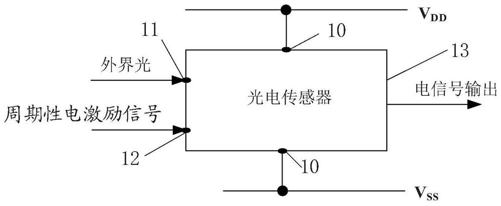
[0077] see image 3 , the present application provides an actively driven photoelectric sensor, including a power supply terminal 10, a first terminal 11, a second terminal 12 and a photosensitive output part 13, which will be described in detail below.
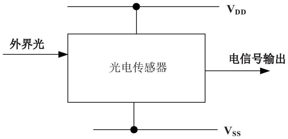
[0078] The power supply terminal 10 is used to receive power supply, including the high voltage input terminal V DD and low voltage input V SS , to provide electrical energy for the dynamic-driven photoelectric sensor.
[0079] The first terminal 11 is used to receive external light, so that the sensing element of the actively driven photoelectric sensor can output a corresponding electrical signal according to the external light.
[0080] The second terminal 12 is used to receive a periodic electrical excitation signal to modulate and optimize the output of the electrical signal of the photoelectric sensor by adding different waveforms of the periodic electrical excitation signal. The periodic electrical excitation signal ...
Embodiment 2
[0098] Such as Figure 7 , the present application provides a driving method for an actively driven photoelectric sensor, including step S10 to step S30, which will be described in detail below.
[0099] Step S10: receiving a periodic electrical excitation signal.
[0100] Step S20: adjusting the illumination threshold according to the periodic electrical excitation signal.
[0101] Step S30: Modulating the output of the electrical signal according to the illumination threshold and the received external light.
[0102] In the embodiment of the present invention, a periodic electrical excitation signal is applied to the active-driven photoelectric sensor, wherein the periodic electrical excitation signal includes a voltage signal or a current signal, and the active-driven photoelectric sensor The light threshold is adjusted, and then the output of the electrical signal is modulated according to the light threshold and the received external light. When the illumination thresh...
Embodiment 3
[0111] see Figure 10 , the present application provides a front-end circuit of a photoelectric sensor system, including a filter circuit 02, an operational amplifier circuit 03, and the above-mentioned photoelectric sensor 01, which will be described in detail below.
[0112] The photoelectric sensor 01 includes a power supply terminal, a first terminal, a second terminal and an optical sensor output part, the specific content of which is consistent with that of Embodiment 1, and will not be described again.
[0113] The filtering circuit 02 is used to filter the output electrical signal and output the filtered signal;
[0114] The operational amplifier circuit 03 is used to amplify the filtered signal and output the amplified signal.
[0115] In one possible implementation manner, the front-end circuit of the photoelectric sensing system further includes: an ADC analog-to-digital converter 04 , configured to perform analog-to-digital conversion on the received amplified sig...
PUM
 Abstract
Description
Claims
Application Information
 - R&D
- Intellectual Property
- Life Sciences
- Materials
- Tech Scout
- Unparalleled Data Quality
- Higher Quality Content
- 60% Fewer Hallucinations
Browse by: Latest US Patents, China's latest patents, Technical Efficacy Thesaurus, Application Domain, Technology Topic, Popular Technical Reports.
© 2025 PatSnap. All rights reserved.Legal|Privacy policy|Modern Slavery Act Transparency Statement|Sitemap|About US| Contact US: help@patsnap.com