Fretting fatigue surface crack detection method and system

A technology for fretting fatigue and surface cracks, which is applied in the direction of applying repetitive force/pulsation force to test material strength, measuring devices, and testing of mechanical components. It can solve the impact of sample fatigue life, cannot effectively measure cracks, and has low monitoring accuracy. And other issues

Pending Publication Date: 2020-03-27
AECC COMML AIRCRAFT ENGINE CO LTD
View PDF5 Cites 4 Cited by
  • Summary
  • Abstract
  • Description
  • Claims
  • Application Information

AI Technical Summary

Problems solved by technology

[0005] 1. The in-situ SEM monitoring method requires prefabricated cracks on the fatigue specimen, which makes it impossible to capture crack initiation and small crack propagation
[0006] 2. The resolution of the real-time image monitoring method is low, and its accuracy cannot observe the initiation and expansion of small cracks on the surface
[0007] 3. The monitoring accuracy of the potential method and the strain gauge monitoring method is too low to effectively measure small-scale cracks
[0009] The inventors have found that this method has several disadvantages: first, the film shrinks by about 10% after it is completely air-dried
Second, the acetone used in the lamination process will have a certain impact on the fatigue life of the sample
Third, the lamination process of cellulose acetate film is very cumbersome, and it usually takes 20-30 minutes from the beginning of lamination to the complete air drying of the film; and in order to prevent the influence of small defects that occasionally appear on the surface of the film, it is usually necessary to repeat lamination many times

Method used


Image

  • Fretting fatigue surface crack detection method and system
  • Fretting fatigue surface crack detection method and system
  • Fretting fatigue surface crack detection method and system

Examples


Embodiment Construction

[0053] Combine below Figure 1 to Figure 6 The technical solution provided by the present invention is described in more detail.

[0054] First introduce the nouns or terms involved in this article.

[0055] Fretting fatigue: refers to the fact that a component or material is subject to fretting damage on a certain part of the surface on the one hand, and on the other hand, it also bears a large external fatigue load. Break failure.

[0056] Surface crack (stress concentration): refers to the formation or propagation of cracks on the surface of components or materials.

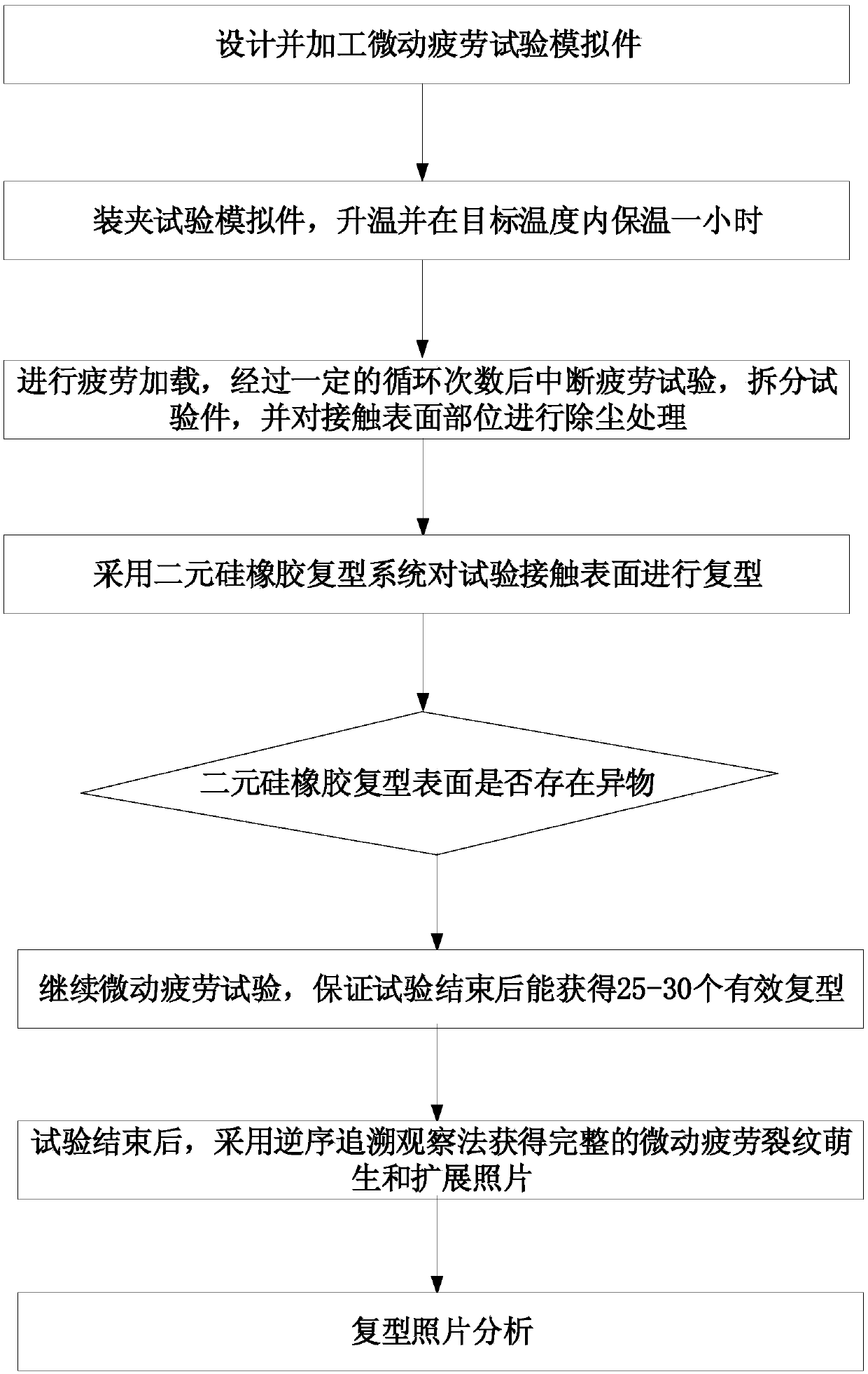
[0057] see image 3 , an embodiment of the present invention provides a method for detecting fretting fatigue surface cracks, comprising the following steps:

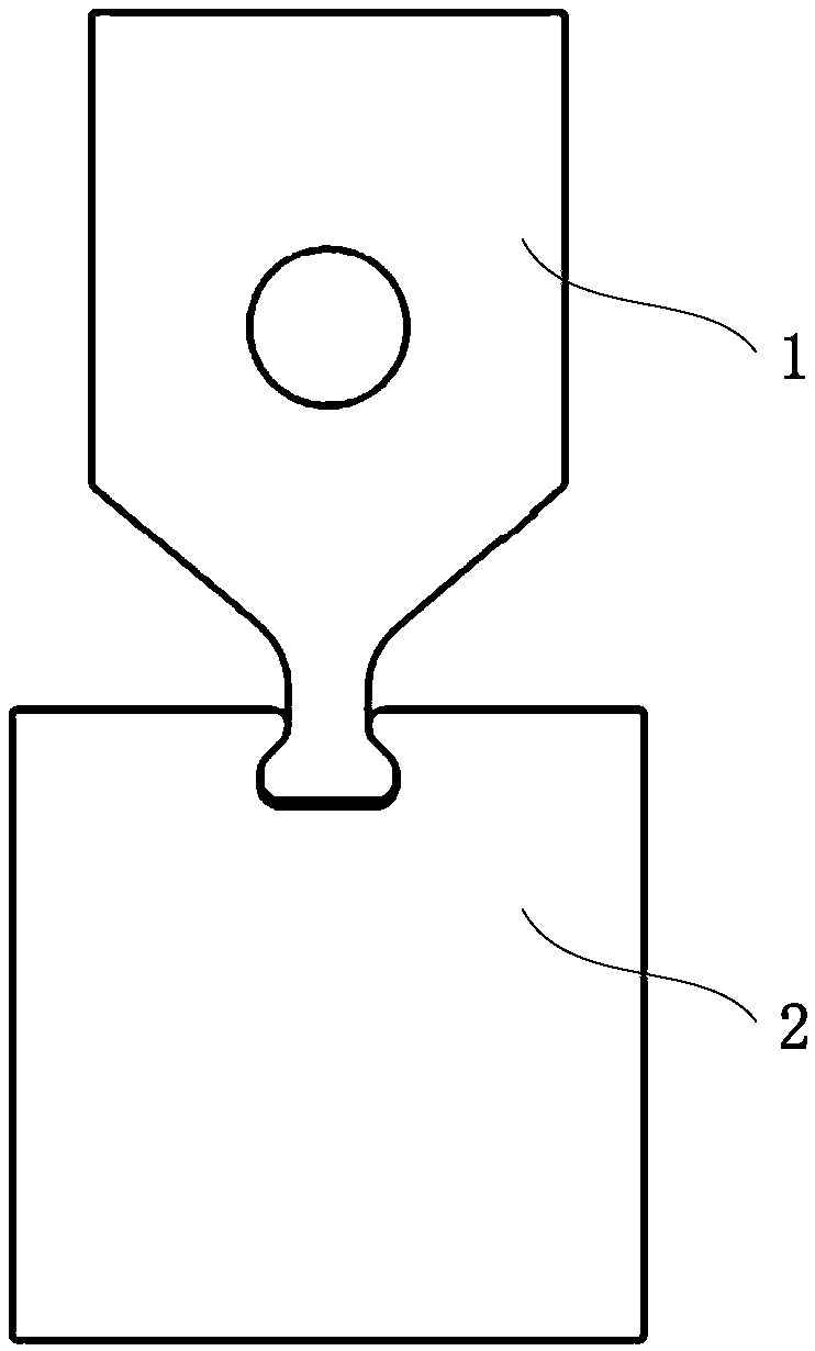
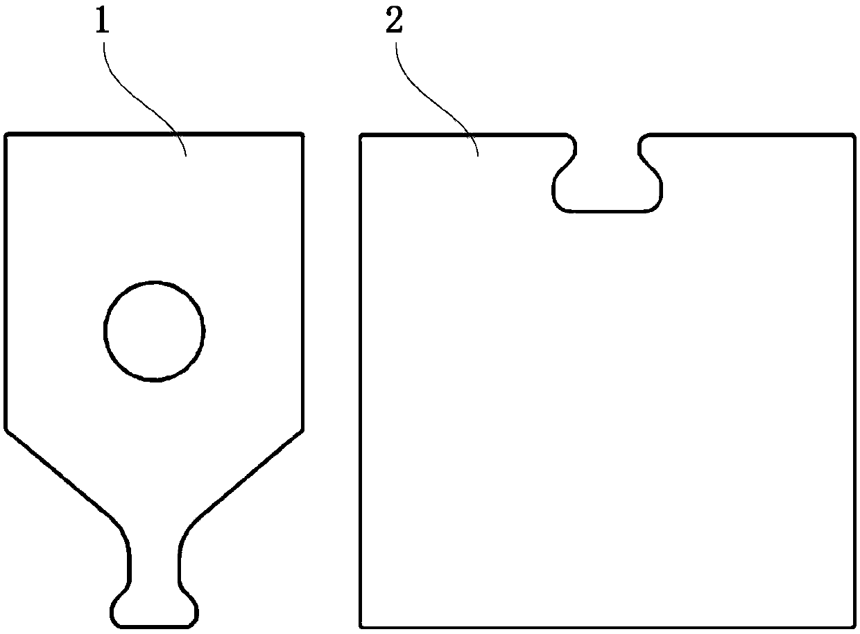
[0058] Step S10 , performing fatigue loading for a set number of times on the two cooperating first component 1 and second component 2 .

[0059] In some embodiments, the first part 1 comprises a tenon and the second part 2 comprises a tongue and g...


PUM


Abstract

The invention discloses a fretting fatigue surface crack detection method and system, relates to the field of fatigue crack monitoring, and is used for simply and conveniently observing fatigue crackinitiation and small crack propagation of a fatigue sample. The method comprises the following steps: carrying out fatigue loading on a first part and a second part which are matched with each other for set times; separating the two first parts and the second part; laminating the mutual contact parts of the first part and the second part with binary silicone rubber to obtain a to-be-observed diaphragm; and repeating the steps until the fretting fatigue test is finished so as to obtain all to-be-observed diaphragms for fretting fatigue analysis. According to the technical scheme, the mutual contact parts of the first part and the second part are respectively laminated by adopting binary silicon rubber; binary silicone rubber laminating is adopted, the curing time is short, shrinkage is avoided after curing, and it is guaranteed that the laminated sheet can accurately reflect cracks on a test; and the method has no influence on the fatigue life of the sample.

Description

technical field [0001] The invention relates to the field of fatigue crack monitoring, in particular to a method and system for detecting fretting fatigue surface cracks. Background technique [0002] In aero-engines and aircraft, many components fail due to fretting fatigue fractures, some of which are key components, such as the tenon connection of the compressor and the turbine, the connection of the case, the connection of the disc and the shaft, etc. In order to improve the life of related components of aero-engines and reduce or avoid the occurrence of fretting fatigue failure, it is necessary to study the mechanism of fretting fatigue crack initiation and small crack growth. [0003] However, how to realize the effective monitoring of fretting fatigue crack initiation and small crack propagation of components and samples has always been a difficult problem in the industry. The inventors found that the reason is that the fretting damage occurs at the surface contact o...

Claims


Application Information

Patent Timeline
Patent Type & Authority Applications(China)
IPC IPC(8): G01N3/32G01M13/00
CPCG01M13/00G01N3/32G01N2203/0073
Inventor 邓国坚张成成侯乃先高靖云任远
Owner AECC COMML AIRCRAFT ENGINE CO LTD
Why Eureka
Try Eureka