Transmission interface circuit based on SUBLVDS

A transmission interface and circuit technology, applied in the direction of logic circuit interface device, logic circuit connection/interface layout, etc., can solve the problems of oscillation attenuation, poor impedance matching performance, affecting transmission quality, etc., to reduce ringing and overshoot, The output common mode is stable and the effect of enhancing signal quality

Active Publication Date: 2020-03-27
JILIN UNIV
View PDF8 Cites 2 Cited by
  • Summary
  • Abstract
  • Description
  • Claims
  • Application Information

AI Technical Summary

Problems solved by technology

[0004] Conventional SUBLVDS output interface such as figure 1 As shown, the disadvantages of this structure are as follows: First, due to the existence of the external terminal resistance, when the signal passes through the transmission line with sudden change in resistance, it will cause serious signal reflection and poor impedance matching performance; second, the output common mode of the signal cannot Hold, the output cannot be received stably; third, due to the parasitic capacitance and inductance on the transmission line, the response signal often has overshoot and oscillation attenuation, which affects the transmission quality

Method used


Image

  • Transmission interface circuit based on SUBLVDS
  • Transmission interface circuit based on SUBLVDS
  • Transmission interface circuit based on SUBLVDS

Examples


Embodiment Construction

[0029] Specific embodiments of the present invention will be described in detail below in conjunction with the accompanying drawings. It should be understood that the specific embodiments described here are only used to illustrate and explain the present invention, and are not intended to limit the present invention.

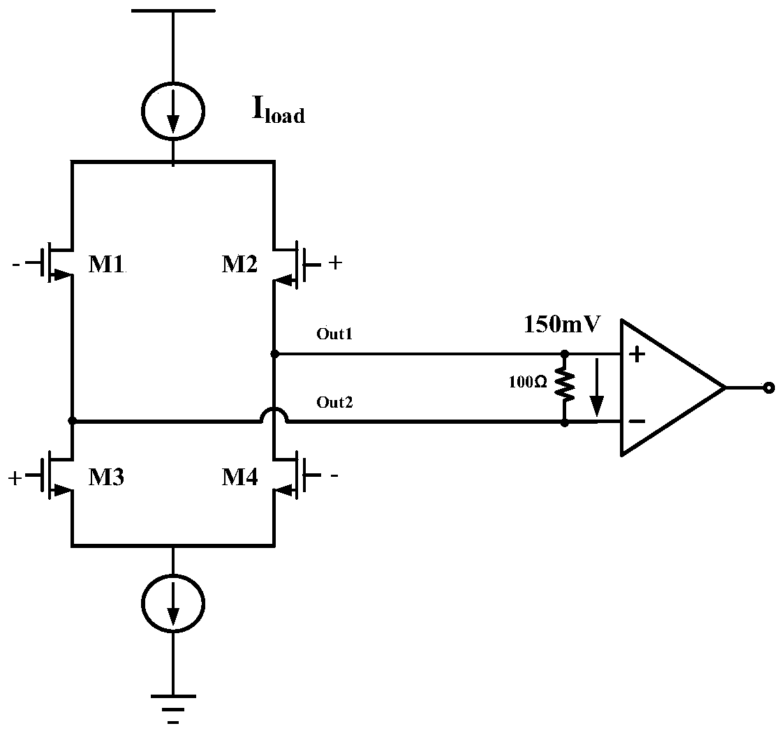
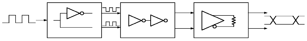
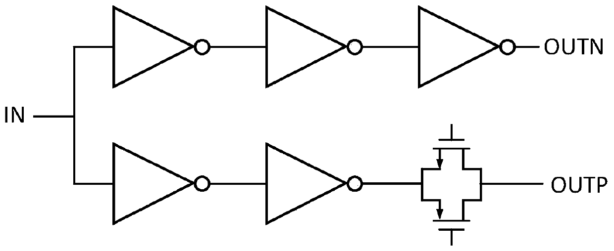
[0030]A transmission interface circuit based on SUBLVDS, used to transmit high-speed signals inside the chip to the outside of the chip, including a single-ended to differential module, an input buffer module and a common-mode feedback output drive module; the single-ended to differential module is used to convert The input single-ended signal is converted into a differential signal and output to the input buffer module; the input buffer module sends the received differential signal to the common-mode feedback output drive module after passing through the two-stage buffer to improve the signal drive capability; the common-mode The feedback output driver module c...


PUM


Abstract

The invention provides a high-speed transmission interface circuit based on the SUBLVDS technology, and belongs to the technical field of integrated circuits. The circuit mainly comprises three parts:a single-ended to differential module, an input buffer module and a common-mode feedback output driving module. The circuit is used for converting a single-ended signal in a chip into a pair of low-voltage differential signals meeting the SUBLVDS protocol standard and outputting the pair of low-voltage differential signals to the outside of the chip at a high speed. The circuit can work under thelow voltage of 1.2 V, the output swing amplitude is 150 mV, the transmission speed is high, and the cable can be used for high-frequency signal transmission. And meanwhile, the driver circuit with aslew rate compensation structure is adopted, and an adjustable internal terminal resistor is added, so that the impedance matching performance of the circuit is greatly improved, the overshoot and ringing phenomena of transmission signals are greatly reduced, and the transmission quality is improved. A common-mode feedback loop is formed in the circuit, so that an output common mode is stable, andan output signal can be stably received.

Description

technical field [0001] The invention belongs to the technical field of integrated circuits, and in particular relates to a transmission interface circuit based on SUBLVDS. Background technique [0002] With the rapid development of information technology today, the high-speed transmission of signals has become an important part of the information world. Since it is difficult for high-speed signals to be directly transmitted from the inside of the chip to the outside of the chip, there is a large difference in the data transmission speed inside and outside the chip, and this difference becomes an important factor affecting system performance. Adopting low-voltage, low-swing high-speed data transmission interface is an effective way to solve this problem. [0003] The LVDS interface is an interface technology that uses low-voltage and low-swing differential signals to achieve high-speed data transmission between point-to-point, and has the advantages of high speed, low power ...

Claims


Application Information

Patent Timeline
Patent Type & Authority Applications(China)
IPC IPC(8): H03K19/0175
CPCH03K19/017509Y02D10/00
Inventor 殷景志石梦涵常玉春蒋佳奇
Owner JILIN UNIV
Why Eureka
Try Eureka