

Semiconductor integrated circuit
A technology of integrated circuits and semiconductors, applied in the field of semiconductor integrated circuits, which can solve the problem of sacrificing the operating speed of class D amplifiers
- Summary
- Abstract
- Description
- Claims
- Application Information
AI Technical Summary
Problems solved by technology
Method used
Image

Examples
Embodiment 1
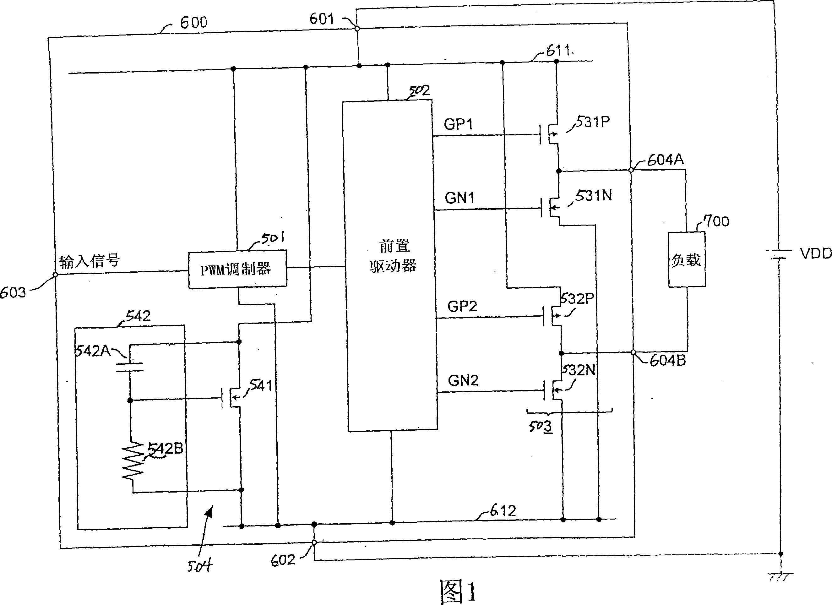
[0023] FIG. 1 is a circuit diagram showing the structure of a class D amplifier 600 according to Embodiment 1 of the semiconductor integrated circuit of the present invention. The class D amplifier 600 has a high potential power supply terminal 601, a low potential power supply terminal 602, an input terminal 603, and output terminals 604A and 604B. The high-potential power supply terminal 601 is connected to the positive electrode of the power supply VDD, and the low-potential power supply terminal 602 is connected to the negative electrode of the power supply VDD and grounded. In the example shown in the figure, a single power supply is used. For this reason, the low potential power supply terminal 602 is grounded. However, in the case of using the structure described below, even if the structure uses a power supply generating a positive power supply voltage and a power supply generating a negative power supply voltage, it is preferable that the high-potential power supply ...
Embodiment 2
[0035] 6 and 7 are circuit diagrams showing configurations of a class D amplifier 100A having ringing reduction circuits 40NA and 40PA according to Embodiment 2 of the present invention. FIG. 6 shows the circuit configuration of the ringing reduction circuit 40NA, and FIG. 7 shows the circuit configuration of the ringing reduction circuit 40PA.
[0036] The class D amplifier 100A has a high potential power supply terminal 101 , a low potential power supply terminal 102 , an input terminal 103 and an output terminal 104 . The high potential power supply terminal 101 is connected to the positive electrode of the power supply VDD via the high potential power supply line 131 arranged outside the class D amplifier 100A, and the low potential power supply terminal 102 is connected to the power supply VDD via the low potential power supply line 132 arranged outside the class D amplifier 100A. negative and grounded. In the illustrative example, since a single power supply is used, th...
Embodiment 3
[0048] 9 and 10 show configuration circuit diagrams of a class D amplifier 100B having ringing reduction circuits 40PB and 40NB according to Embodiment 3 of the present invention. FIG. 9 shows the circuit configuration of the ringing reduction circuit 40NB, and FIG. 10 shows the circuit configuration of the ringing reduction circuit 40PB. In FIGS. 9 and 10 , components having corresponding components to those of FIGS. 6 and 7 referred to above are hereafter provided with the same reference symbols and will not be described again.
[0049] In Embodiment 2, the comparators 410 and 420 as ringing detectors detect the output signal by comparing the level of the output line 120 with the level PVDDI of the high-potential power supply line 111 or the level PVSSI of the low-potential power supply line 112 Ringing occurs in OUT.
[0050] However, when the switching current of the output buffer circuit 30 flows through the parasitic inductance 141 or 142, a huge counter electromotive f...
PUM
 Abstract
Description
Claims
Application Information