
Receiver optical assemblies (ROAS) having photo-detector remotely located from transimpedance amplifier, and related components, circuits, and methods

a technology of photodetector and optical assembly, which is applied in the direction of optical elements, electromagnetic transceivers, instruments, etc., can solve the problems of increasing the cost of active optical cables over traditional copper cables having the same shorter length, the higher cost of active optical cables for shorter cable distances is not perceived as providing enough value to consumers to justify the increased cost over traditional copper cables. , to achieve the effect of reducing the cost of the roa, increasing bandwidth, and increasing costs

Active Publication Date: 2014-04-24
CORNING OPTICAL COMM LLC +1
View PDF1 Cites 6 Cited by
  • Summary
  • Abstract
  • Description
  • Claims
  • Application Information

AI Technical Summary

Benefits of technology

The patent text describes a new design for receiver optical assemblies (ROAs) that reduces costs and allows for higher bandwidth operation. The new design uses a differential transimpedance amplifier (TIA) circuit with a higher input impedance, which prevents ringing effects and reduces capacitance components. The transmission circuit is designed to match the TIA input impedance. The technical effects of this design include increased bandwidth, reduced noise, and lower costs.

Problems solved by technology

For shorter length active optical cable, the additional component costs contribute a greater percentage of the overall cost of the active optical cable thereby resulting in a more expensive cable over traditional copper cables having the same shorter length.
Thus, active optical cables have not been typically designed for use in consumer applications at shorter lengths (e.g., consumer electronic devices, personal computers, external hard drives, digital cameras, and televisions).
The higher cost of active optic cables for shorter cable distances is not perceived as providing enough value to consumers to justify the increased cost over traditional copper cables.
Thus, there is an unresolved need for short-haul active optical cables suitable for use in consumer applications that benefit from the increased bandwidth and low noise operation of optical fiber and that are commercially viable.

Method used


Image

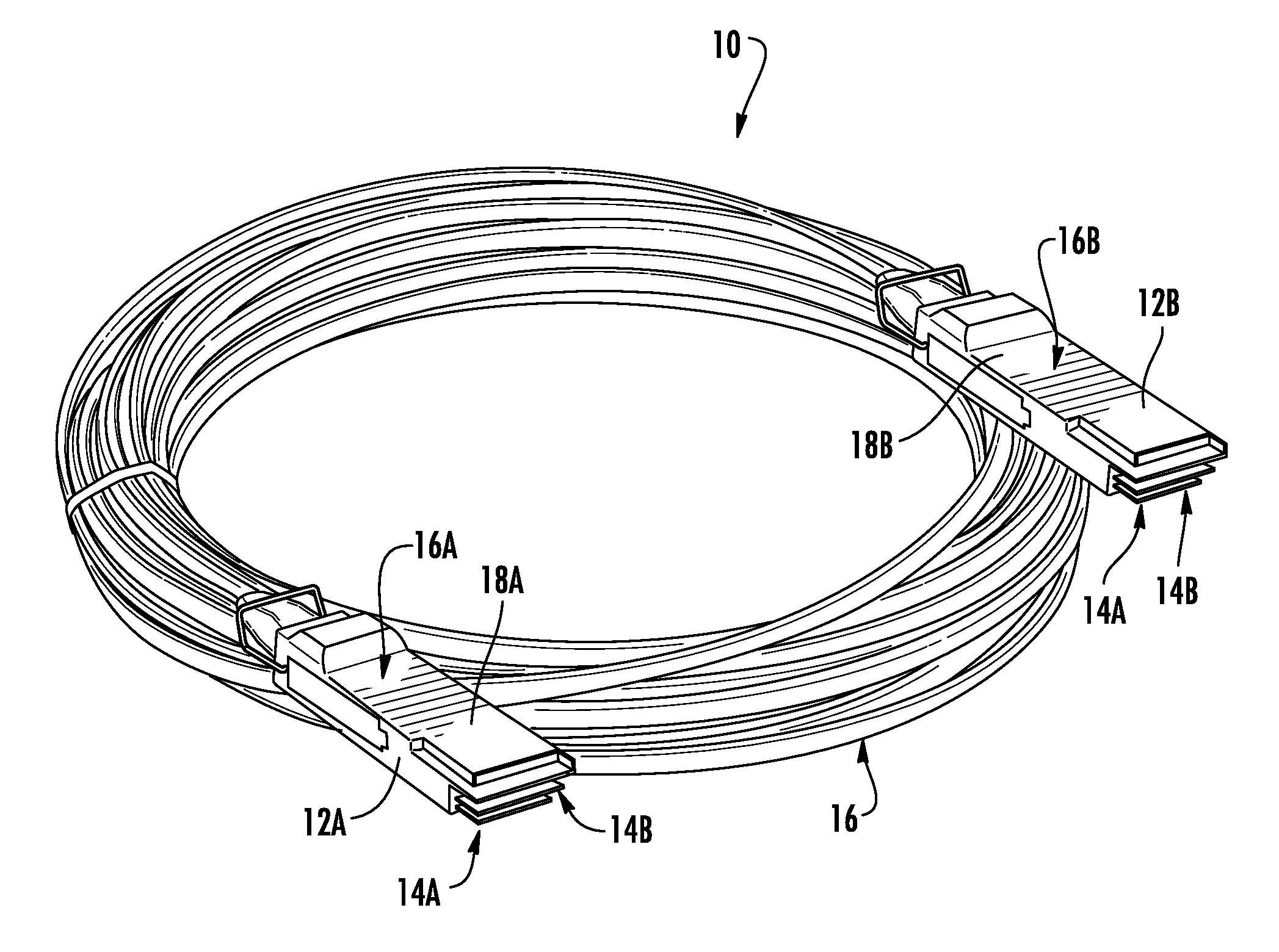
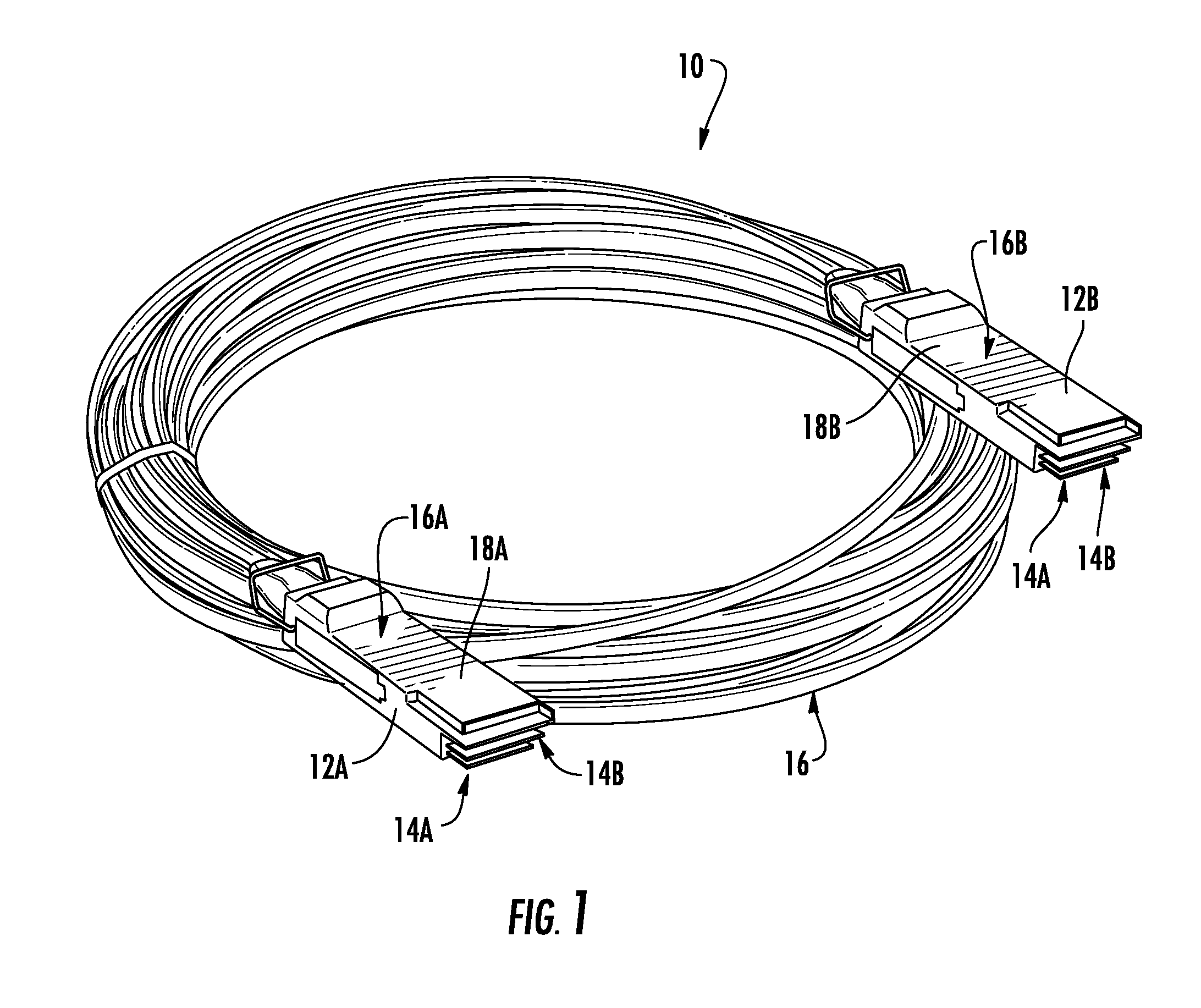
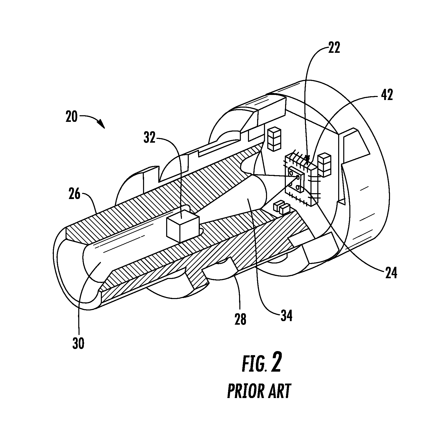
  • Receiver optical assemblies (ROAS) having photo-detector remotely located from transimpedance amplifier, and related components, circuits, and methods
  • Receiver optical assemblies (ROAS) having photo-detector remotely located from transimpedance amplifier, and related components, circuits, and methods
  • Receiver optical assemblies (ROAS) having photo-detector remotely located from transimpedance amplifier, and related components, circuits, and methods

Examples


Embodiment Construction

[0009]Embodiments disclosed herein include receiver optical assemblies (ROAs) having a photo-detector remotely located from transimpedance amplifier (TIA). Related components, circuits, and methods are also disclosed. The ROA concepts of the present application use design differences that are contrary to conventional ROSA designs for conventional long-haul applications. For instance, by providing the photo-detector remotely located from a TIA, additional costs associated with conventional design constraints of providing the photo-detector intimate with a TIA may be avoided, thereby reducing the cost of the ROA. For example, expensive bonding assembly techniques to directly connect a photo-detector to a TIA may be avoided. In this regard as a non-limiting example, the ROAs according to the embodiments disclosed herein may allow shorter haul active optical cable applications to be more readily accepted for use in consumer applications from a cost standpoint with the added benefits of ...


PUM

PropertyMeasurementUnit
input impedanceaaaaaaaaaa

Abstract

Embodiments disclosed herein include receiver optical assemblies (ROAs) having a photo-detector remotely located from a differential transimpedance amplifier (TIA). Related components, circuits, and methods are also disclosed. By providing the photo-detector remotely located from a TIA, additional costs associated with design constraints of providing the photo-detector intimate with a TIA may be avoided, thereby reducing cost of the ROA. In this regard as a non-limiting example, the ROAs according to the embodiments disclosed herein allow shorter haul active optical cable applications for use in consumer applications from a cost standpoint with the added benefits of increased bandwidth and low noise performance of optical fiber. In this regard, the ROAs disclosed herein provide higher input impedance differential TIA circuits and transmission circuits inhibiting or reducing ringing effects and maintain a sufficiently low resistance-capacitance (RC) time constant for differential TIA circuit to allow for higher bandwidth operation of the ROA.

Description

RELATED APPLICATIONS[0001]This application claims the benefit of priority under 35 U.S.C. §119 of U.S. Provisional Application Ser. No. 61 / 716,868 filed on Oct. 22, 2012, the content of which is relied upon and incorporated herein by reference in its entirety.BACKGROUND[0002]1. Field of the Disclosure[0003]The technology of the disclosure relates to receiver optical sub-assemblies (ROSA) that receive optical signals from an optical fiber and convert the received optical signals into electrical signals.[0004]2. Technical Background[0005]As interconnect line speeds increase, such as five (5) to ten (10) Gigabits per second (Gbps), and beyond, active optical cables (AOCs) are increasingly being used as an alternative to traditional copper cables. Active optical cables allow electrical signals to be converted and carried as optical signals over optical fiber. Benefits of utilizing optical fiber include extremely wide bandwidth and high immunity to environmental electronic noise.[0006]In...

Claims


Application Information

Patent Timeline
Patent Type & Authority Applications(United States)
IPC IPC(8): G02B6/42H05K3/30
CPCH05K3/30G02B6/4295H04B10/40H04B10/693Y10T29/49128
Inventor COLE, ANDREWGALLOWAY, BRIAN JEFFREYMANCA, JOSEPH PETER JOHNWALKER, RICHARD CLAYTON
Owner CORNING OPTICAL COMM LLC
Learn More