
Method and apparatus for damping an ultrasonic transducer suitable for time of flight ranging and level measurement systems

a technology of ultrasonic transducers and level measurement systems, applied in the direction of mechanical vibration separation, instruments, and using reradiation, can solve the problems of difficult, if not impossible, to measure echo pulses or distances close to the transducer, and achieve the effect of reducing the ringing in the transducer

Active Publication Date: 2007-03-27
SIEMENS AG
View PDF13 Cites 7 Cited by
  • Summary
  • Abstract
  • Description
  • Claims
  • Application Information

AI Technical Summary

Benefits of technology

"The present invention provides a method and apparatus for damping a transducer used in time of flight ranging systems and level measurement systems. The invention includes a damper component that is bonded to the transducer using a plasma etched surface, which absorbs vibrations and reduces ringing in the transducer. This results in improved accuracy and reliability of the level measurement system."

Problems solved by technology

The blanking characteristic makes it difficult, if not impossible, to measure echo pulses, or distances close to the transducer, because of the ringing effects.

Method used


Image

  • Method and apparatus for damping an ultrasonic transducer suitable for time of flight ranging and level measurement systems
  • Method and apparatus for damping an ultrasonic transducer suitable for time of flight ranging and level measurement systems
  • Method and apparatus for damping an ultrasonic transducer suitable for time of flight ranging and level measurement systems

Examples


Embodiment Construction

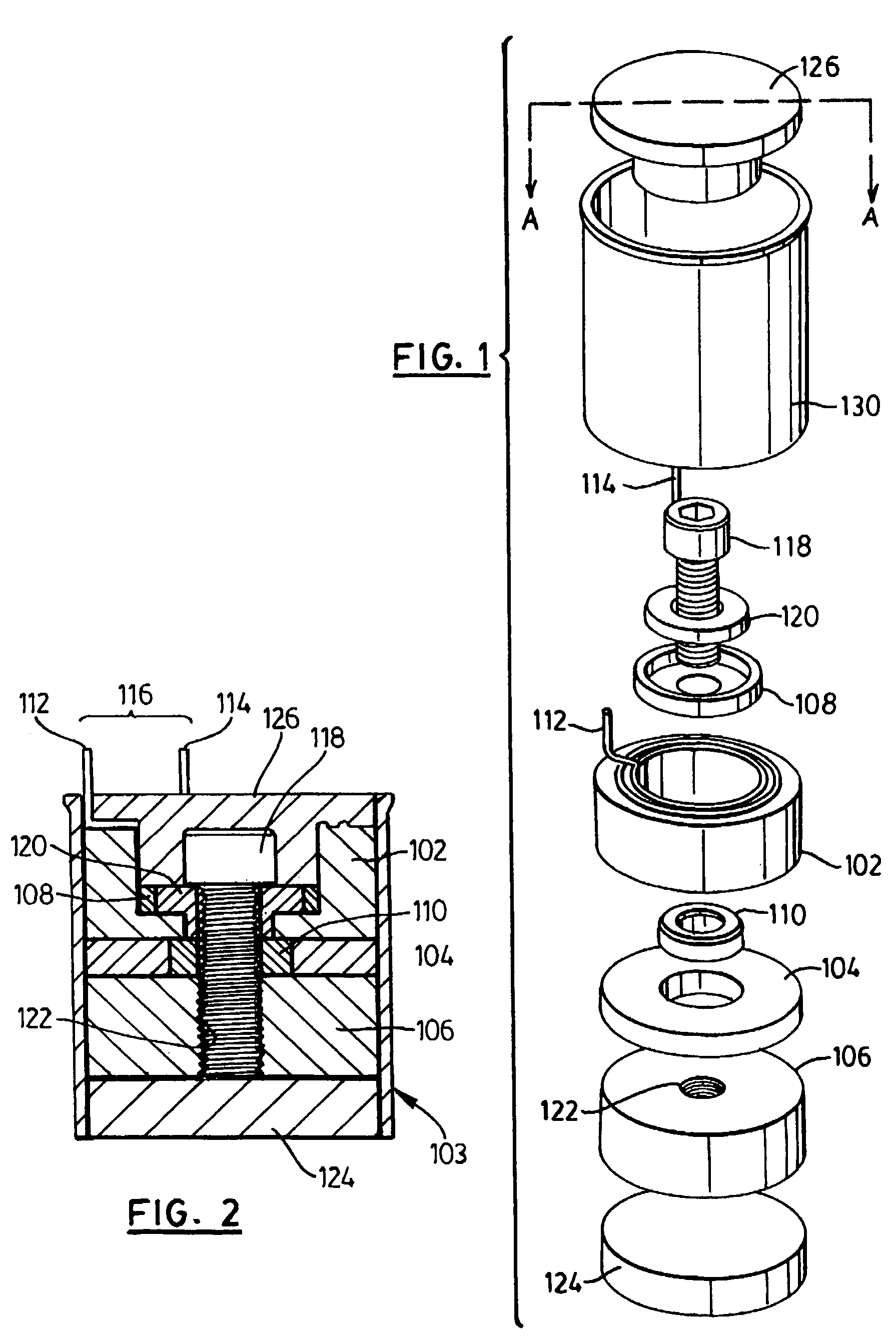
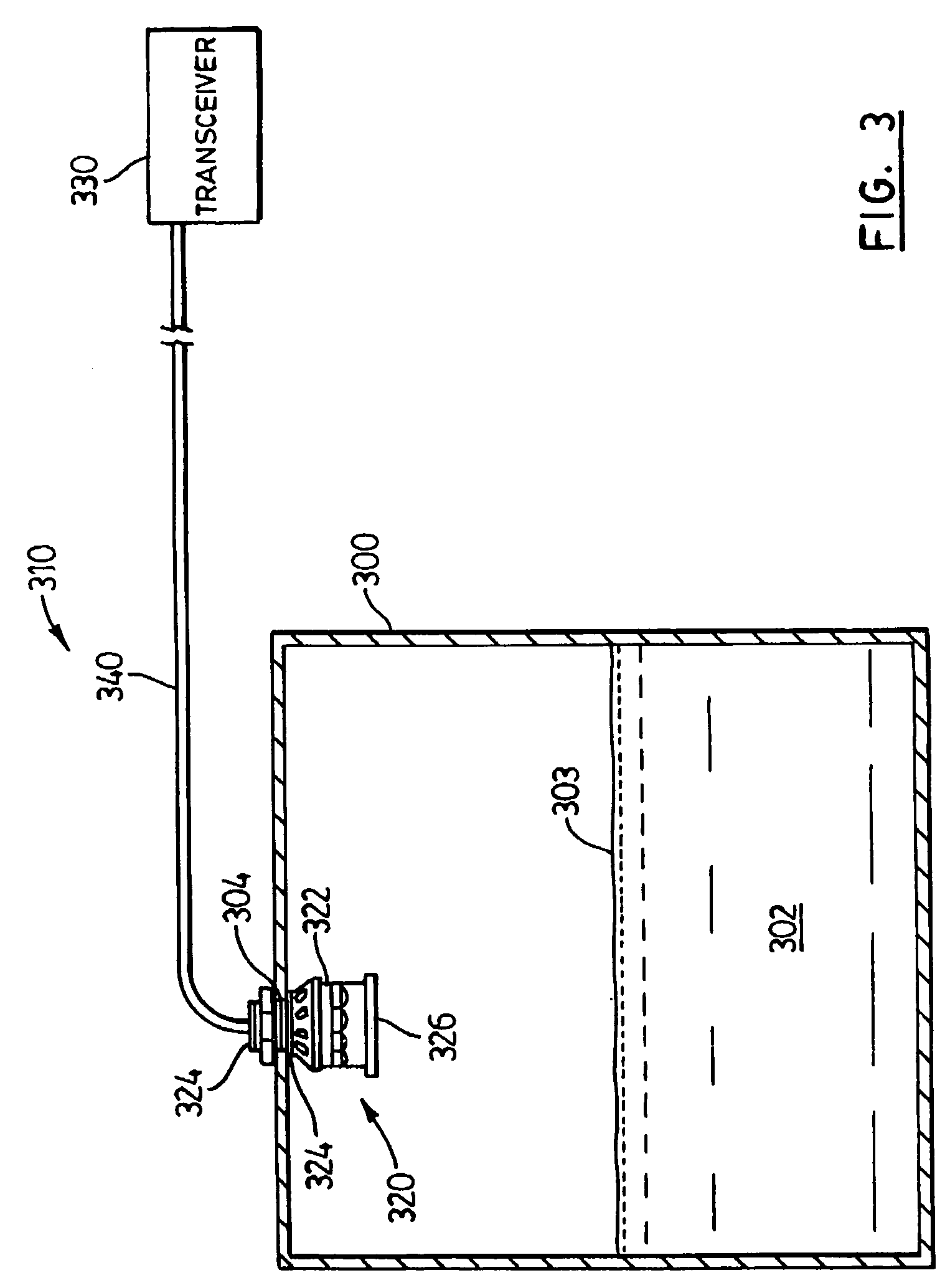
[0015]Reference is first made to FIG. 1, and also the sectional view in FIG. 2, which shows an ultrasonic transducer in accordance with the present invention and indicated generally by reference 100. The ultrasonic transducer 100 according to this aspect is suitable for use in a level measurement system as described in more detail below with reference to FIG. 3.

[0016]As shown in the exploded view of FIG. 1, the transducer 100 comprises a loading block 102, a ceramic ring 104, a metal disc 106, an insulating cap 108, and a damping washer 110. The ceramic ring 104 is sandwiched between the loading block 102 and the metal disc 106. The ceramic ring 104 includes an interior opening into which the damping washer 110 fits or sits. A metal terminal 112 is coupled to the loading block 102. The metal terminal 112 together with another metal terminal 114 form an input / output port, indicated by reference 116, for applying excitation pulses to the transducer elements and for outputting signals ...


PUM


Abstract

A method and apparatus for damping an ultrasonic transducer suitable for time of flight ranging and level measurement systems. The ultrasonic transducer comprises a damping component which absorbs vibrations in the transducer to reduce the ringing effect. The damping component is subjected to plasma etching to produce a surface which readily bonds to component(s) of the transducer. According to one aspect, the damping component is formed from an inert elastomer, such as silicone rubber, and the transducer component is made of stainless steel.

Description

FIELD OF THE INVENTION[0001]The present invention relates to time-of-flight ranging systems and level measurement systems, and more particularly to a method and apparatus for damping a transducer for a time of flight ranging system and a level measurement system.BACKGROUND OF THE INVENTION[0002]The transducers utilized in ultrasonic based time of flight ranging systems and level measurement systems experience ringing which results from the continuation of vibrations that occur after the excitation pulse or input is ended. The ringing gives rise to a characteristic known as blanking. The blanking characteristic makes it difficult, if not impossible, to measure echo pulses, or distances close to the transducer, because of the ringing effects.[0003]Better damping to decrease the ringing allows the blanking distance to be reduced. This in turn provides the level measurement system the capability to provide a greater measurement range, i.e. ranging from the target surface in the vessel t...

Claims


Application Information

Patent Timeline
Patent Type & Authority Patents(United States)
IPC IPC(8): H04R17/00G01S15/00G01S15/08G10K11/00
CPCG01S15/08G10K11/002Y10S367/908
Inventor TRAFFORD, MARK
Owner SIEMENS AG
Learn More