

Centering disk and loudspeaker with centering disk
A technology of centering struts and loudspeakers, which is applied in the field of electroacoustics, can solve the problems of high rigidity, easy fatigue fracture failure of the conductive layer, etc., and achieve the effect of reducing structural rigidity, preventing failure risk, and reducing maximum stress
- Summary
- Abstract
- Description
- Claims
- Application Information
AI Technical Summary
Problems solved by technology
Method used
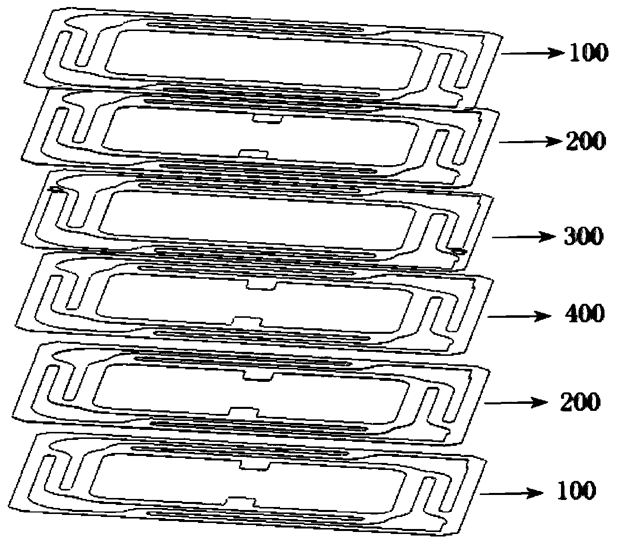
Image

Examples
Embodiment 1
[0043] A centering support piece, which adopts a multi-layer structure composed of multiple material layers or a multi-layer structure composed of multiple material layers and glue layers. The material layer includes a conductive layer located in the center area and a conductive layer located on the outer surface. The substrate layer, the substrate layer can be a polyimide film (PI film), and the conductive layer can be a copper foil. The copper foil is adhered to the polyimide film coated with an adhesive by a rolling process, or not Use an adhesive to produce copper foil directly on the polyimide film.
[0044] The base material layer is not limited to the above-mentioned polyimide film (PI film), and other polymer material films other than polyimide can also be used, and the conductive layer is not limited to the above-mentioned copper foil. It is another metal layer or graphene conductive layer.
[0045] It is explained that the centering support piece is a six-layer layered s...
Embodiment 2
[0061] The same part of the content as in Embodiment 1 has been discussed in detail in Embodiment 1, and will not be repeated here. Compared with Embodiment 1, this embodiment is modified as follows:
[0062] The shape of the hollow area 3 is an irregular geometric shape.
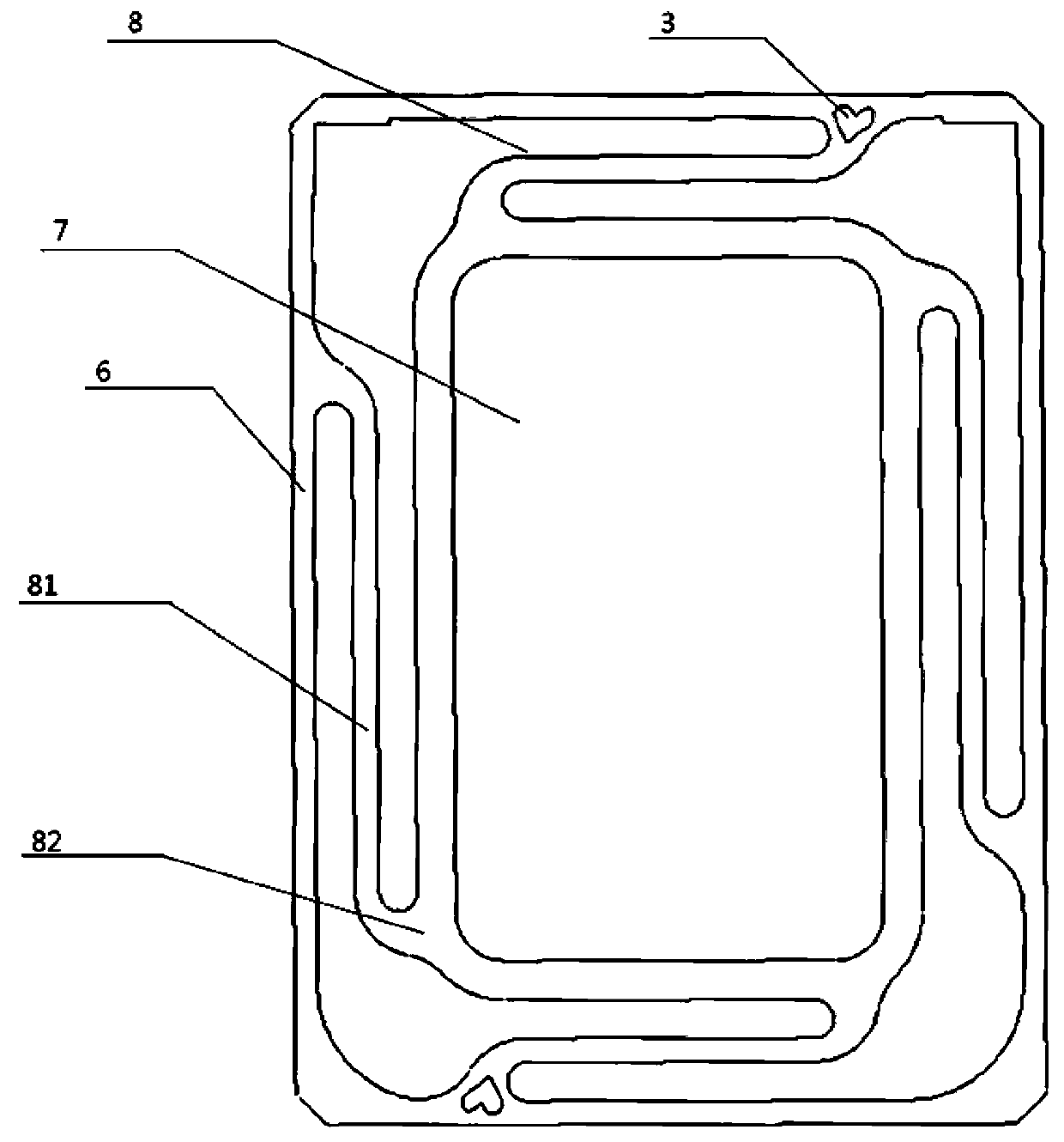
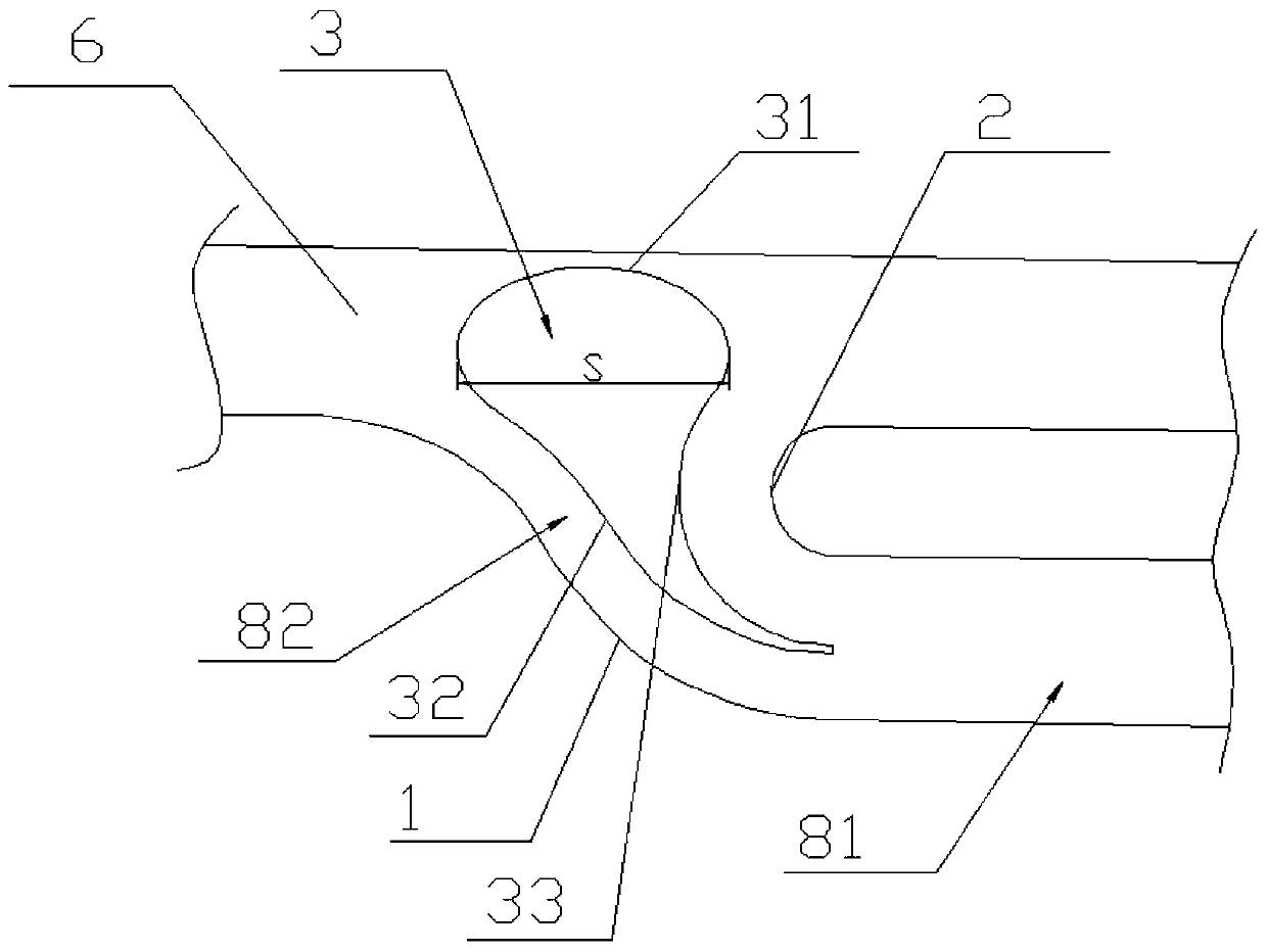
[0063] Preferably, such as image 3 As shown, the root portion 82 of the conductive layer is provided with an outer arc edge portion 1 and an inner arc edge portion 2, the area between the outer arc edge portion 1 and the inner arc edge portion 2 is provided with a hollow area 3, and the outer arc edge portion 1 One end and one end of the inner arc side portion 2 are both extended to connect to the cantilever body 81, and the other end of the outer arc side portion 1 and the other end of the inner arc side portion 2 are both extended to connect to the first fixing portion 6.
[0064] The hollow area 3 is surrounded by a first connecting edge portion 31, a second connecting edge portion 32, and a third connecting e...
Embodiment 3
[0071] The same part of the content as in Embodiment 1 has been discussed in detail in Embodiment 1, and will not be repeated here. Compared with Embodiment 1, this embodiment is modified as follows:
[0072] The hollow area 3 is an irregular geometric shape.
[0073] Preferably, such as image 3 As shown, the root 82 of the conductive layer is provided with an outer arc edge portion 1 and an inner arc edge portion 2, the area between the outer arc edge portion 1 and the inner arc edge portion 2 is provided with a hollow area 3, and the outer arc edge portion 1 One end and one end of the inner arc side portion 2 are both extended to connect to the cantilever body 81, and the other end of the outer arc side portion 1 and the other end of the inner arc side portion 2 are both extended to connect to the first fixing portion 6.
[0074] The hollow area 3 is surrounded by a first connecting edge portion 31, a second connecting edge portion 32, and a third connecting edge portion 33. Both ...
PUM
 Abstract
Description
Claims
Application Information