Fluidized bed semi-drying desulfurization system and method

A desulfurization system and fluidized bed technology, applied in the field of fluidized bed semi-dry desulfurization systems, can solve the problems of unfavorable pre-dust removal device dust removal efficiency, poor pre-dust removal device dust removal performance, etc., and achieve enhanced dust removal effect and better operation performance. Best, performance-enhancing effects

Active Publication Date: 2020-03-31
江苏天莱环保工程有限公司
View PDF6 Cites 0 Cited by
  • Summary
  • Abstract
  • Description
  • Claims
  • Application Information

AI Technical Summary

Problems solved by technology

[0006] In order to solve the above problems, the present invention provides a fluidized bed semi-dry desulfurization system and method, which effectively avoids the disadvantages of the adsorption tank body in the pre-dust removal device in the prior art, which is not conducive to replacement and the pre-dust removal device after a long period of use. Poor dust removal performance, which is not conducive to the dust removal effect of the pre-dust removal device

Method used


Image

  • Fluidized bed semi-drying desulfurization system and method
  • Fluidized bed semi-drying desulfurization system and method
  • Fluidized bed semi-drying desulfurization system and method

Examples


Embodiment 1

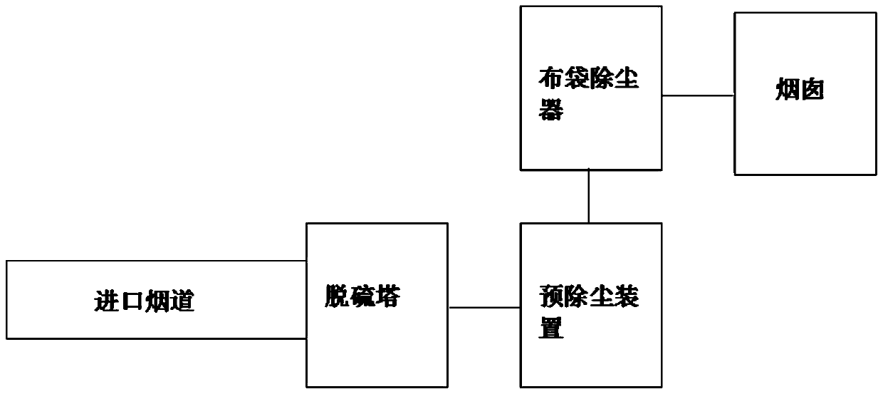
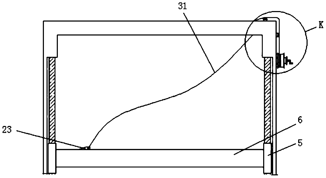
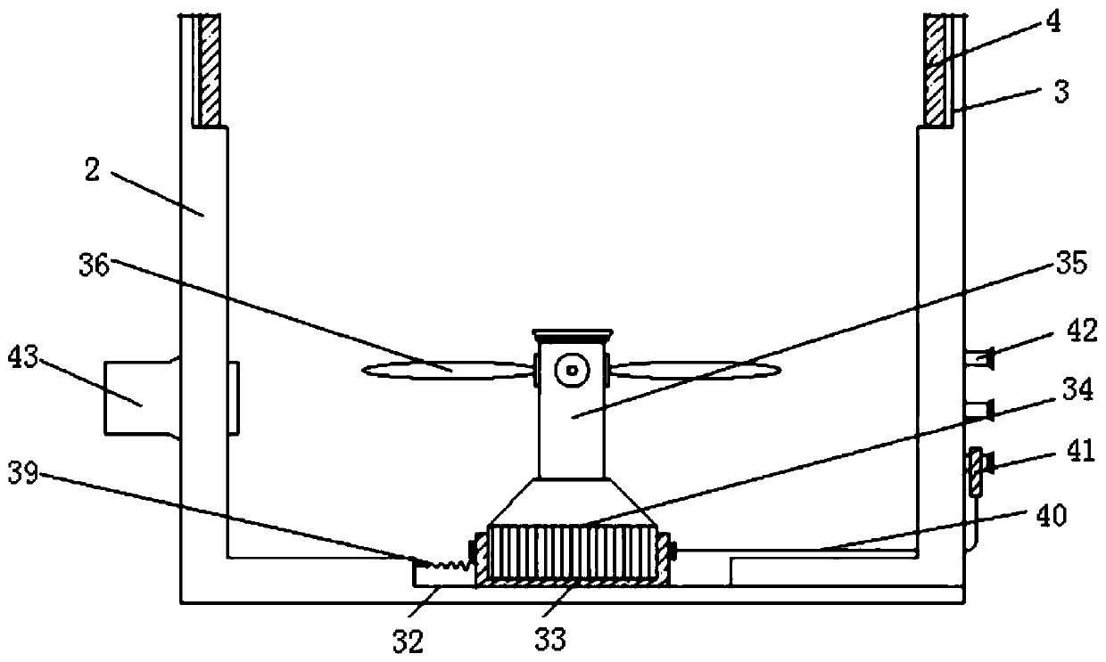
[0037] Such as Figure 1-Figure 6As shown, the fluidized bed semi-dry desulfurization system includes a pre-dust removal device connected with a desulfurization tower and a bag filter; the pre-dust removal device includes a hollow shell 2, and both sides of the inner surface of the hollow shell 2 are Guide rails 3 are provided, the number of the guide rails 3 is a pair, and the vertical center line of the hollow shell 2 is used as a mirror image line to mirror the distribution between the other pair of guide rails 3, and the inner surface of the guide rails 3 Both the upper end and the lower end are fixedly connected with the guide column 4 by welding, and the upper end of the guide column 4 is provided with a ring-shaped guide plate 5, and the other pair of guide plates 5 are fixedly connected with a disc-shaped disc-shaped body. 6. The upper end of the disc-shaped body 6 is sequentially provided with an insertion port 22, a cylindrical opening 7 and a cuboid opening 8 from o...

Embodiment 2

[0039] Fluidized bed semi-dry desulfurization system, including a pre-dust removal device connected with a desulfurization tower and a bag filter; the pre-dust removal device includes a hollow shell 2, and guide rails are provided on both sides of the inner surface of the hollow shell 2 3. The number of the guide rails 3 is a pair, and the other pair of guide rails 3 are distributed in a mirror image with the vertical center line of the hollow shell 2 serving as a mirror line. The upper and lower ends of the inner surface of the guide rails 3 All are fixedly connected with the guide column 4 by welding, the upper sleeve of the guide column 4 is provided with a ring-shaped guide plate 5, and the other pair of guide plates 5 are fixedly connected with a disc-shaped disc-shaped body 6, so The upper end of the disc-shaped body 6 is sequentially provided with an insertion port 22 , a cylindrical opening 7 and a cuboid opening 8 from one side to the other. The cylindrical opening 7 a...


PUM

PropertyMeasurementUnit
Caliberaaaaaaaaaa

Abstract

Fluidized bed semi-drying desulfurization system and method. The system includes a pre-dust removal apparatus connected to a desulfurization column and a bag-type dust remover, wherein the pre-dust removal apparatus includes a hollow shell, wherein a pair of guide rails are arranged on the two sides of the inner surface of the hollow shell, and the other pair of guide rails are distributed in a mirror arrangement with the vertical central line of the hollow shell being a mirror line. Guide columns are fixedly arranged between the upper end and the lower end of the inner surface of each guide rail. A guide plate sleeves each guide column. A disc body is fixedly connected between the other pair of the guide plates. By means of other structures or methods, the system can avoid the defects that an adsorption tank body is difficult to replace in a pre-dust removal apparatus in the prior art, which causes poor dust removal performance of the pre-dust removal apparatus after a certain operation period and adverse effect on dust removal effect of the pre-dust removal apparatus.

Description

technical field [0001] The invention relates to the technical field of fluidized bed, and also to the technical field of semi-dry desulfurization, in particular to a fluidized bed semi-dry desulfurization system and method. Background technique [0002] The circulating fluidized bed flue gas desulfurization process is a new semi-dry technology developed by Lurgi Company in Germany in the late 1980s. This process is based on the principle of circulating fluidized bed, through repeated recirculation of the absorbent, prolonging the contact time between the absorbent and the flue gas, greatly improving the utilization rate of the absorbent and the desulfurization efficiency. The circulating fluidized bed flue gas desulfurization process is similar to the circulating fluidized bed boiler, which makes the bed reach a state of intense turbulence, thereby enhancing the absorption of sulfur dioxide by the absorbent. [0003] Furthermore, circulating fluidized bed semi-dry desulfuri...

Claims


Application Information

Patent Timeline
IPC IPC(8): B01D50/00B01D53/80B01D53/50
CPCB01D50/00B01D53/80B01D53/50B01D2258/0283
Inventor 陈治国杨义球赵起
Owner 江苏天莱环保工程有限公司
Why Eureka
Try Eureka