Cast-aluminum rotor die-casting die and die-casting process thereof
A technology for die-casting molds and cast aluminum rotors, applied in the field of die-casting molds, can solve the problems of insufficient die-casting, not easy to demold, not enough convenience, etc., and achieve the effects of good preheating, good mold fixing, and easy demoulding.
- Summary
- Abstract
- Description
- Claims
- Application Information
AI Technical Summary
Problems solved by technology
Method used
Image

Examples
Embodiment 1
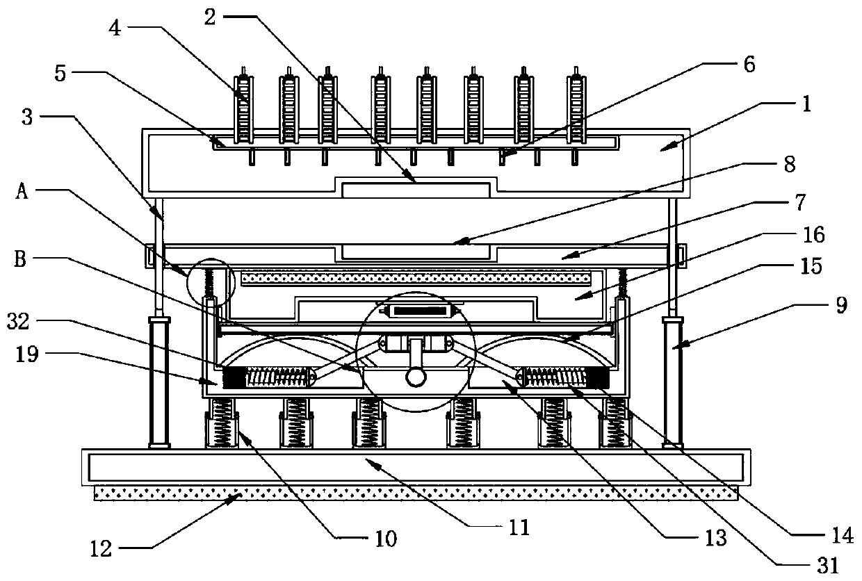
[0031] Such as Figure 1-Figure 5 As shown, a cast aluminum rotor die-casting mold provided in this embodiment includes a base 11 and third buffer components 10 installed on the top of the base 11 and distributed at equal intervals. A U-shaped seat 19 is installed on the top of the third buffer component 10 . Limiting chute 13 is all opened at the bottom four corners of U-shaped seat 19 inner sides, and the inboard of limiting chute 13 is equipped with first cushioning assembly 31, and U-shaped seat 19 bottom middle positions are equipped with fixed block 22, and the first buffering assembly 31 is hinged with a hinged rod 21 away from the inside wall of the limit chute 13, and the end of the hinged rod 21 away from the first buffer assembly 31 is hinged with a sliding top block 20, and the top of the sliding top block 20 is equipped with a sliding limit plate 29, U-shaped The top of seat 19 inner side is equipped with limit slide rail 30, and the inboard of limit slide rail 30...
Embodiment 2
[0042] A die-casting process of a cast aluminum rotor die-casting mold, comprising the following steps:
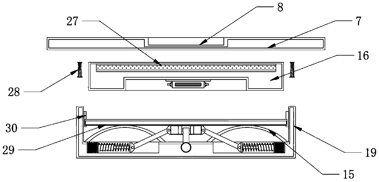
[0043] Step 1: spraying release liquid through the inner side of the downward mold groove 8;
[0044] Step 2: heating the electric heating plate 27 by starting the electric heater 23, and preheating the fixed template 7 through the electric heating plate 27;
[0045] Step 3: Start the electro-hydraulic cylinder 9 to drive the movable template 1 to move downwards so that the upper mold groove 2 and the lower mold groove 8 are engaged;
[0046] Step 4: Press and hold the fixed template 7 by the movable template 1 to drive the compression of the second buffer assembly 28 and the third buffer assembly 10, and drive the sliding top block 20 to move downward;
[0047] Step 5: The hinged rod 21 is driven by the downward movement of the sliding top block 20 , and the first buffer component 31 is pushed by the hinged rod 21 for further buffering.
PUM
 Abstract
Description
Claims
Application Information
 - R&D Engineer
- R&D Manager
- IP Professional
- Industry Leading Data Capabilities
- Powerful AI technology
- Patent DNA Extraction
Browse by: Latest US Patents, China's latest patents, Technical Efficacy Thesaurus, Application Domain, Technology Topic.
© 2024 PatSnap. All rights reserved.Legal|Privacy policy|Modern Slavery Act Transparency Statement|Sitemap