
A kind of copper pipe welding method

A welding method and technology for copper tubes, applied in welding equipment, welding equipment, auxiliary welding equipment, etc., can solve the problems of short fusion line length of welding joints, welding wire piercing copper tubes, poor physical properties, etc., and achieve long fusion line , Improve the physical properties, the effect of low porosity

Active Publication Date: 2022-07-19
CHINA NAT ELECTRIC APP RES INST
View PDF7 Cites 0 Cited by
  • Summary
  • Abstract
  • Description
  • Claims
  • Application Information

AI Technical Summary

Problems solved by technology

[0004] The traditional wire feeder uses a DC motor as the drive unit, and uses the DC wire feeding method to weld the copper tube. The welding wire does not completely melt when it touches the copper tube, and it will exert pressure on the tube wall of the copper tube. When the thin-walled copper tube is heated at a high temperature, The physical properties become worse. Under the pressure of the welding wire, the copper tube is easy to melt and corrode, resulting in thinning of the tube wall. In severe cases, the welding wire will puncture the copper tube
In addition, the solder formed after the welding wire is melted cannot completely flow into the weld seam, and a welding bump will be formed on the surface of the copper tube. The contact area between the welding wire and the copper tube will dissolve and shrink, and the length of the fusion line of the welded joint will be short.

Method used


Image

  • A kind of copper pipe welding method
  • A kind of copper pipe welding method

Examples


Embodiment

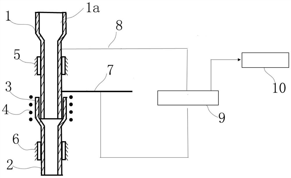
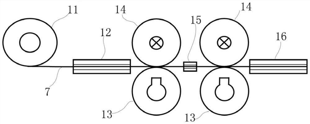
[0030] like figure 1 As shown, the copper pipe welding device of the present invention comprises a first clamp 5 and a second clamp 6, the first clamp 5 is used for clamping the first copper pipe 1 to be welded, and the second clamp 6 is used for clamping the For the second copper tube 2, the welding joints 3 of the first copper tube 1 and the second copper tube 2 have matching sockets. The welding device further includes a heating coil 4 and a wire feeder. The heating coil 4 is welded around the The joint 3 is provided for local heating of the welding joint 3. The wire feeder uses a stepper motor to provide a power source to transport the welding wire 7, and the welding wire 7 is connected to a signal wire 8, and one end of the signal wire 8 is connected to the first copper wire 8. The tube 1 is connected in contact, so that a closed loop can be formed between the welding wire 7, the signal wire 8 and the first copper tube 1. The signal wire 8 is also connected with a PLC con...


PUM

PropertyMeasurementUnit
thicknessaaaaaaaaaa
lengthaaaaaaaaaa

Abstract

The present invention provides a copper pipe welding method. The welding device of the method includes a first clamp and a second clamp. The first clamp is used to clamp the first copper pipe to be welded, and the second clamp is used to clamp the first copper pipe to be welded. The second copper pipe to be welded is clamped, the welding joints of the first copper pipe and the second copper pipe have matching sockets, and the welding device also includes a heating coil and a wire feeder, and the heating coil surrounds The welding joint is set, the wire feeder uses a stepping motor to provide a power source to transport the welding wire, and the welding wire is connected to a signal line, and one end of the signal line is connected to the first copper tube. Contact connection, so that a closed loop can be formed between the welding wire, the signal wire and the first copper tube, the signal wire is also connected with a PLC controller, and the PLC controller monitors whether the welding wire is connected to the The first copper tube contact described above. The invention can transport the welding wire in liquid phase in a step-by-step manner to improve the welding quality.

Description

technical field [0001] The invention relates to a method for welding copper pipes. Background technique [0002] In the refrigeration industry, most of the heat exchange pipes of electrical equipment such as refrigerators and air conditioners are copper pipes. The connection quality of copper pipe welding has always been a focus of attention in the refrigeration industry. [0003] The main indicators that reflect the connection quality of copper pipe joints are: joint strength, air tightness and corrosion resistance. Brazing is usually used to connect copper pipes. Brazing is a welding method that uses liquid solder to fill the gaps of solid workpieces to connect metals. During the welding process, the solder melts but the weldment does not melt, the welding deformation is small, and the joint is smooth and beautiful. In the prior art, the brazing material can be fed to the welding joint position of the copper pipe by a wire feeder. The main factors affecting the welding jo...

Claims


Application Information

Patent Timeline
Patent Type & Authority Patents(China)
IPC IPC(8): B23K31/02B23K37/00B23K103/12B23K101/14
CPCB23K31/02B23K37/00B23K2103/12B23K2101/14
Inventor 王玲万超符永高曹诺胡嘉琦刘阳
Owner CHINA NAT ELECTRIC APP RES INST
Learn More