Preparation device and process of cement-based material with regularly arranged hole structure
What is AI technical title?
AI technical title is built by Patsnap AI team. It summarizes the technical point description of the patent document.
A technology for cement-based materials and preparation devices, applied in clay preparation devices, cement mixing devices, unloading devices, etc., can solve problems affecting actual preparation, etc., and achieve low cost, high mechanical strength and good effect
Inactive Publication Date: 2020-03-31
JIANGXI UNIV OF TECH
View PDF4 Cites 2 Cited by
Summary
Abstract
Description
Claims
Application Information
AI Technical Summary
This helps you quickly interpret patents by identifying the three key elements:
Problems solved by technology
Method used
Benefits of technology
Problems solved by technology
[0004] Based on this, the purpose of the present invention is to solve the problem that in the prior art, the existing cement-based material preparation device does not have a mechanism that can control the feeding of the raw materials after stirring and the bucket placed on the loading plate when feeding. The mechanism by which the clamping is carried out, causing problems affecting the actual preparation
Method used
Image
Click on the blue label to locate the original text in one second.
Reading with bidirectional positioning of images and text.
Examples
Embodiment 1
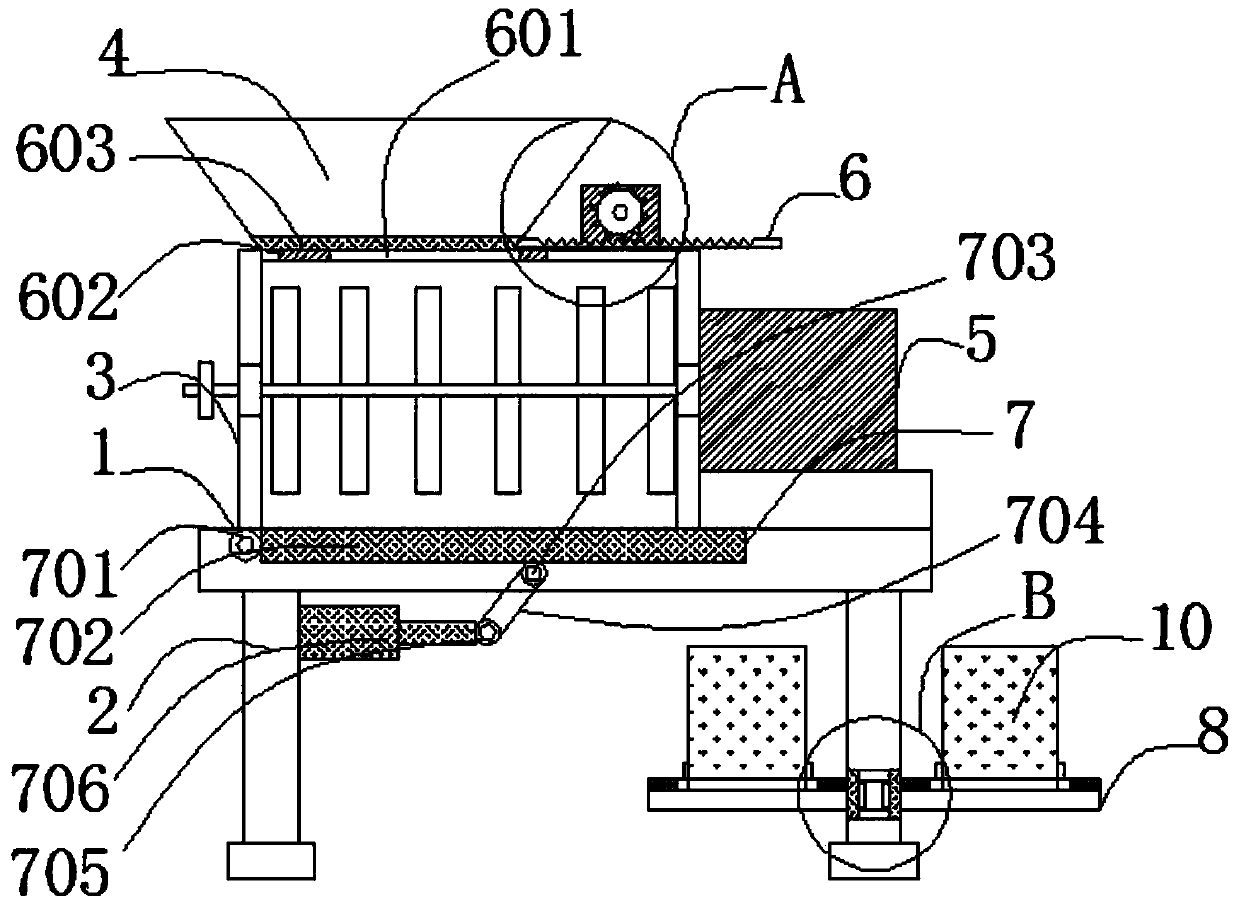
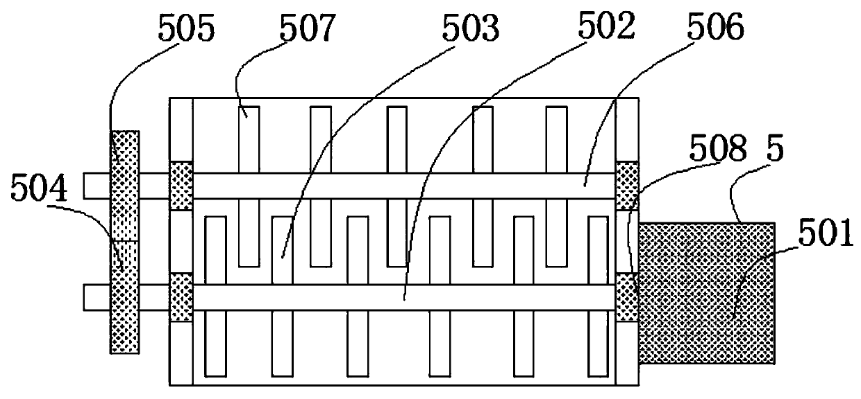
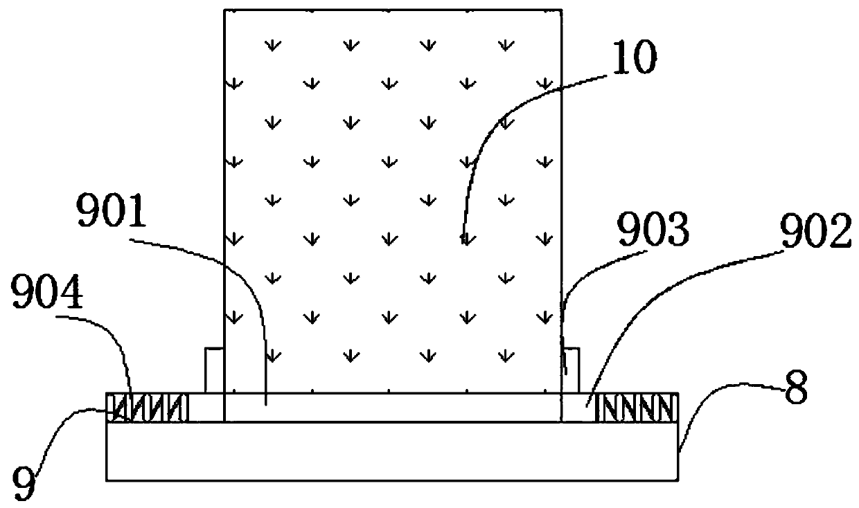
[0038] See Figure 1 to Figure 5 , The present invention provides a cement-based material preparation device with a regularly arranged hole structure, which includes a workbench 1, a bottom support 2, a mixing box 3, a feed hopper 4, a mixing mechanism 5, a first drive motor 501, a first Connecting shaft 502, first mixing blade 503, first gear 504, second gear 505, second connecting shaft 506, second mixing blade 507, bearing 508, controllable material mechanism 6, first chute 601, first sliding Block 602, partition 603, toothed rod 604, second slider 605, third gear 606, rotating shaft 607, second drive motor 608, discharge mechanism 7, first movable shaft 701, movable plate 702, second movable Shaft 703, movable rod 704, third movable shaft 705, electric push rod 706, bearing plate 8, clamping mechanism 9, second sliding groove 901, third sliding block 902, splint 903, spring 904, barrel 10, rotation The mechanism 11, the inner magnetic column 1101, the third sliding groove ...
Embodiment 2
[0052] The present invention also proposes a process for preparing cement-based materials with a regularly arranged hole structure, which mainly includes 3 steps:
[0054] The details of step 1 are as follows: stir and pour 100g of Portland cement, 10g of ordinary glass powder and 25g of tap water into the feed hopper 4, and then use the controllable feed mechanism 6 to determine the size of the feed inlet of the raw material into the mixing box 3 Adjustment is convenient to control the speed of raw materials entering the mixing box 3.
[0055] Step 2: The external power supply of the first driving motor 501 is activated to make the first stirring blade 503 and the second stirring blade 507 rotate to stir the raw materials put into the stirring box 3.
[0056] The detailed content of step 2 is...
PUM
Abstract
The invention relates to a preparation device and process of a cement-based material with a regularly arranged hole structure. The preparation device comprises a workbench, the bottom end of the workbench is fixedly connected with a bottom support, and a stirring box is fixedly mounted at the top end of the workbench. The top end of the stirring box is fixedly connected with a feeding funnel. According to the preparation device and process of the cement-based material, under the action of the stirring mechanism, after materials are discharged through the feeding funnel and enter the stirring box, an externa power source of a first driving motor can be started, a first stirring blade connected with a first connecting shaft rotates, meanwhile a first gear connected with the exterior of the first connecting shaft drives a second gear engaged with one side to rotate, and therefore a second connecting shaft drives a second stirring blade to rotate; and stirring is carried out in the mannerthat the first stirring blade and the second stirring blade intersect, the raw materials are better in effect and more even, the effect of the cement-based material in the use process is better, and holes of the porous cement-based material are evenly arranged.
Description
Technical field [0001] The invention relates to the relevant technical field of cement-based material preparation devices, and specifically to a cement-based material preparation device and preparation process. Background technique [0002] Cement-based materials, as the most widely used civil engineering materials, are widely used in civil engineering, water conservancy, transportation and other construction projects. Cement-based materials have the characteristics of low price and easy molding. If cement-based materials can be molded In the process, it is prepared to have a porous structure, and the photocatalyst is loaded in these pores, which can be used for photocatalytic purification of volatile gases. [0003] The existing cement-based material preparation equipment does not have a mechanism that can mix and stir the raw materials uniformly, and does not have a mechanism that can control the raw materials to enter the mixing box, and does not have a mechanism that can contro...
Claims
Application Information
Patent Timeline
Application Date:The date an application was filed.
Publication Date:The date a patent or application was officially published.
First Publication Date:The earliest publication date of a patent with the same application number.
Issue Date:Publication date of the patent grant document.
PCT Entry Date:The Entry date of PCT National Phase.
Estimated Expiry Date:The statutory expiry date of a patent right according to the Patent Law, and it is the longest term of protection that the patent right can achieve without the termination of the patent right due to other reasons(Term extension factor has been taken into account ).
Invalid Date:Actual expiry date is based on effective date or publication date of legal transaction data of invalid patent.

