Check patentability & draft patents in minutes with Patsnap Eureka AI!

Device and method for measuring response time of MEMS infrared detector

An infrared detector and response time technology, applied in the field of infrared detectors, can solve the problem that the time-consuming work of the chopper cannot be ruled out

Pending Publication Date: 2020-03-31
JIANGSU HINOVAIC TECH CO LTD
View PDF0 Cites 1 Cited by
  • Summary
  • Abstract
  • Description
  • Claims
  • Application Information

AI Technical Summary

Problems solved by technology

[0004] Therefore, the technical problem to be solved in the present invention is to overcome the time-consuming defect of measuring the response time of MEMS infrared detectors in the prior art that cannot eliminate the time-consuming work of the chopper, thereby providing a MEMS infrared detector response time measuring device and method

Method used


Image

  • Device and method for measuring response time of MEMS infrared detector
  • Device and method for measuring response time of MEMS infrared detector
  • Device and method for measuring response time of MEMS infrared detector

Examples


Embodiment 1

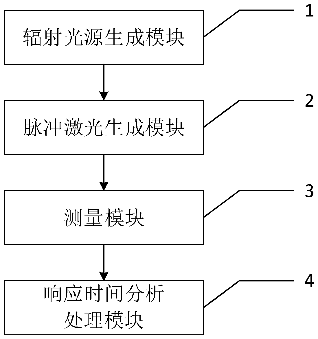
[0033] An embodiment of the present invention provides a device for measuring the response time of a MEMS infrared detector, such as figure 1 As shown, it includes: a radiation source generation module 1, used to generate a radiation source; a pulsed laser generation module 2, used to generate a pulsed laser according to the radiation source, and input it to the MEMS infrared detector; a measurement module 3, used to measure the MEMS infrared The first voltage value and the second voltage value of the detector under different powers of the pulsed laser; the response time analysis and processing module 4 is used to measure the response time of the MEMS infrared detector according to the first voltage value and the second voltage value.

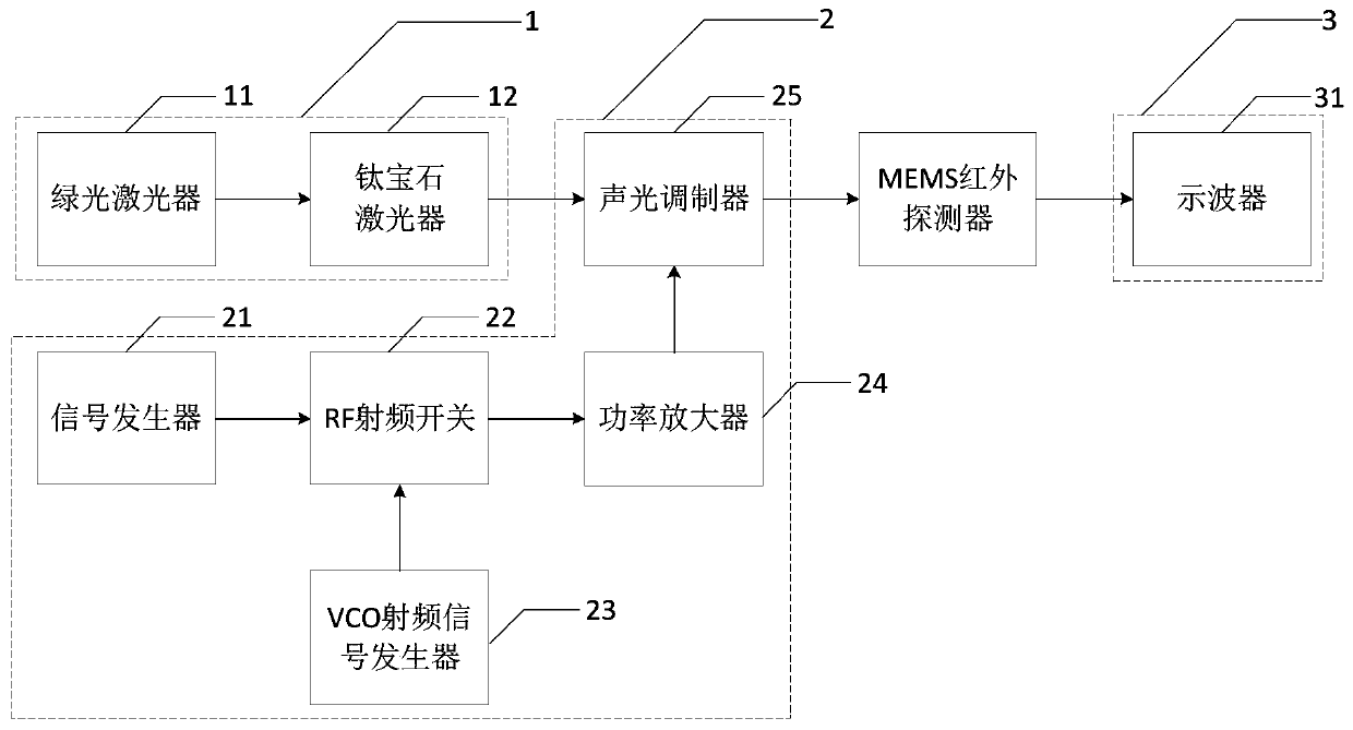
[0034] In an alternative embodiment, such as figure 2As shown, the above-mentioned radiation source generation module 1 includes: a green laser 11 and a Ti:sapphire laser 12, wherein the green laser 11 is used to emit the first outgoing light,...

Embodiment 2

[0053] The embodiment of the present invention provides a method for measuring the response time of a MEMS infrared detector, which is applied to the above-mentioned device for measuring the response time of a MEMS infrared detector, such as Figure 4 shown, including the following steps:

[0054] Step S1: Generate a radiation source by the radiation source generation module 1 .

[0055] The above-mentioned radiation source generating module 1 includes: a green laser 11 and a Ti:sapphire laser 12, the green laser with a wavelength of 532nm is output by the green laser 11 as the pumping source of the Ti:sapphire laser 12, and the Ti:sapphire laser 12 pumps the green laser A radiation source with an output wavelength of 795nm.

[0056] Step S2: Generate pulsed laser light according to the radiation source through the pulsed laser generating module 2, and input it to the MEMS infrared detector.

[0057] The above-mentioned pulsed laser generating module 2 includes: signal gener...


PUM


Abstract

The invention provides a device and method for measuring the response time of an MEMS infrared detector, and the device comprises a radiation light source generation module which is used for generating a radiation light source; a pulse laser generation module which is used for generating pulse laser with adjustable power according to the radiation light source and inputting the pulse laser into the MEMS infrared detector; a measuring module which is used for measuring a first voltage value and a second voltage value of the MEMS infrared detector under different powers of the pulse laser; and aresponse time analyzing and processing module is used for measuring the response time of the MEMS infrared detector according to the first voltage value and the second voltage value. According to theinvention, the problems that in a traditional MEMS infrared detector response time test, the chopper blade shielding-hollowing proportion is not easy to adjust, the blade rotating frequency is difficult to match with a detector, the blade rotating time consumption is long, and the sampling point time interval is large are solved. And the test error of the laser pulse signal is in ns level, so that the accurate test of the response time of the MEMS infrared detector is realized.

Description

technical field [0001] The invention relates to the technical field of infrared detectors, in particular to a MEMS infrared detector response time measuring device and method. Background technique [0002] Micro-Electro-Mechanical System (MEMS) infrared detector takes infrared imaging as the core. It converts infrared radiation into other measurable physical signals, and performs corresponding analog or digital signal processing on the physical signals. Thus, an image that can be visually distinguished by humans is obtained. So far, infrared detection technology has been widely used in military, medical, agricultural, security and other fields. As an important physical quantity of infrared detectors, response time has a great impact on the performance of infrared detectors. [0003] The measurement of the response time of the traditional MEMS infrared detector needs to build a complex measurement system based on black body radiation source, chopper, water cooling device and...

Claims


Application Information

Patent Timeline
IPC IPC(8): G01J5/00G01V13/00
CPCG01J5/00G01V13/00G01J2005/0077G01J5/80
Inventor 张琛琛毛海央陈大鹏
Owner JIANGSU HINOVAIC TECH CO LTD
Features
  • R&D
  • Intellectual Property
  • Life Sciences
  • Materials
  • Tech Scout
  • Unparalleled Data Quality
  • Higher Quality Content
  • 60% Fewer Hallucinations
Learn More