

Real-time detection method for state of split knife switch
A real-time detection, split-type technology, applied in the field of image recognition, can solve the problem of low real-time detection accuracy of the knife switch status
- Summary
- Abstract
- Description
- Claims
- Application Information
AI Technical Summary
Problems solved by technology
Method used
Image

Examples
Embodiment 1
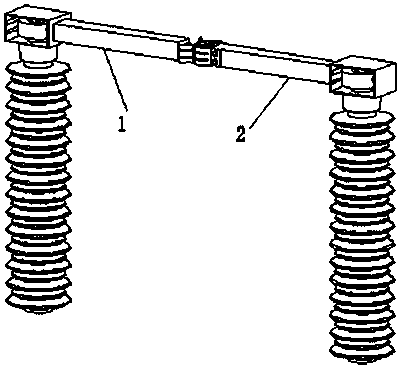
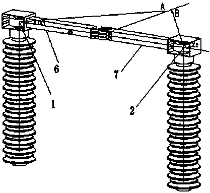
[0045] Embodiment 1: as figure 1 and figure 2 A real-time detection method for the state of a split knife switch is shown, including: collecting a real-time monitoring video of a split knife switch, acquiring each frame of the video image and establishing the model of the split knife switch according to any frame of image The boundary line model of the knife gate arm is saved as a model file, and the midpoint and center line of the knife gate arm are calculated according to the model file; sample images of split knife gates are obtained through various methods, and deep learning is used to train and obtain the sample images Train the model, use the training model to detect the first frame image of the video, obtain all the knife gate areas and knife gate states in the first frame image, and combine the model file to locate the knife gate in the first frame image; according to the above positioning The result is to perform edge detection on the first frame image of the video,...
Embodiment 2
[0047] Embodiment 2: On the basis of Embodiment 1, the center line is used to distinguish the left and right edge line sets of updates, and after obtaining the edge line sets of the left knife gate arm and the edge line set of the right knife gate arm respectively, weight distribution is performed, and the weighted The set of edge lines of the left knife arm and the set of edge lines of the right knife arm are paired symmetrically.
[0048]Embodiment 2 On the basis of Embodiment 1, the weight distribution of the edge line set of the left knife gate arm and the edge line set of the right knife gate arm is carried out, and the knife gate area is identified on the basis of positioning the knife gate area in the first frame image, Then, the identified edge lines of the knife gate are firstly weighted and then symmetrically paired to determine the final left and right knife arm edge lines of the knife gate. In the same way, when processing each frame of image, the knife gate area i...
PUM
 Abstract
Description
Claims
Application Information