
Off-line pipe cutting equipment

A technology for cutting equipment and pipes, which is applied in the field of pipe cutting equipment, which can solve the problems of pipe deviation, influence on laying and use, and pipe skewing, so as to achieve the effect of neat pipes, favorable laying and use, and prevention of deviation

Active Publication Date: 2021-04-27
肇庆新天金属管道有限公司
View PDF7 Cites 0 Cited by
  • Summary
  • Abstract
  • Description
  • Claims
  • Application Information

AI Technical Summary

Problems solved by technology

[0005] Aiming at the deficiencies in the prior art, the purpose of the present invention is to provide an offline pipe cutting equipment to solve the problem that the pipes have different diameters and the positions of the supporting rollers are relatively fixed in the prior art. When the pipe is rotated and cut, it will be in contact with the frame, and the outer surface in contact with the roller is small, so that when the pipe is rotated and cut, it will cause the deviation of the pipe due to touching the frame, resulting in the skew of the cut pipe, which will affect its The problem of laying and using

Method used


Image

  • Off-line pipe cutting equipment
  • Off-line pipe cutting equipment
  • Off-line pipe cutting equipment

Examples


Embodiment 1

[0029] Example 1: Please refer to Figure 1-Figure 7 , the specific embodiments of the present invention are as follows:

[0030] Its structure includes underframe 1, baffle 2, idler 3, moving frame 4, cutting machine 5, adjustment frame 6, said baffle 2 is vertically installed on the upper end of underframe 1 and welded, and said idler 3 is installed Between the partitions 2 and connected by hinges, the mobile frame 4 is horizontally installed on the upper end of the chassis 1 and is movably connected, the cutting machine 5 is installed on the upper end of the mobile frame 4 and is mechanically connected, and the adjustment frame 6 is vertical Installed directly on the inside of the chassis 1 and welded; the adjustment frame 6 includes a lower adjustment structure 61, a support rod 62, an upper adjustment structure 63, and a limit structure 64, and the support rod 62 is vertically installed on the right side of the lower adjustment structure 61. On the other hand, the upper ...

Embodiment 2

[0037] Example 2: Please refer to Figure 7-Figure 10 , the specific embodiments of the present invention are as follows:

[0038] The adaptation structure 643 includes a mounting plate 43a, an adjustment structure 43b, a rotating shaft 43c, and a housing 43d. The adjustment structure 43b is installed between the mounting plates 43a and is mechanically connected. The mounting plate 43a is welded to the lower end of the support plate 642, so that The rotating shaft 43c is embedded in the lower end of the adjustment structure 43b, and the casing 43d is installed on both sides of the mounting plate 43a and welded together.

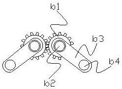
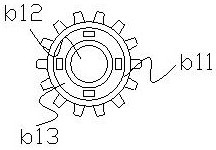
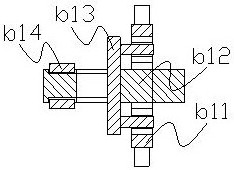
[0039] refer to Figure 8 The adjustment structure 43b includes a gear structure b1, a fixed shaft b2, an adjustment plate b3, and a shaft hole b4. The fixed shaft b2 is embedded and mounted inside the gear structure b1 and engaged with each other. The adjustment plate b3 and the gear structure b1 The center is fixed by the fixed shaft b2, the shaft hole b4...


PUM


Abstract

The invention discloses an off-line cutting equipment for pipes, the structure of which includes a bottom frame, a partition, a roller, a moving frame, a cutting machine, and an adjustment frame. The partition is vertically installed on the upper end of the bottom frame, and the roller is installed between the partition. In between, the mobile frame is installed horizontally on the upper end of the bottom frame, the cutting machine is installed on the upper end of the mobile frame, and the adjustment frame is installed vertically on the inner side of the bottom frame. It is directly installed on the right side of the lower adjustment structure, the upper adjustment structure is horizontally installed on the upper end of the support rod, and the limit structure is installed on the lower end of the upper adjustment structure. The present invention sets an adjustment frame inside the bottom frame to increase the distance between the pipe and the frame , and the cross-section through which the limiting roller contacts is increased, thereby improving the stability of cutting; an adjustment structure is set inside the shell to make it more stable when limited, preventing it from shifting, and thus making the cut out The pipe is more tidy, which is beneficial for subsequent laying and use.

Description

technical field [0001] The invention belongs to the field of pipe material cutting equipment, and in particular relates to an offline pipe material cutting equipment. Background technique [0002] Pipes are mainly used to transport liquid or gas. Among them, the steel-plastic composite pressure pipe used in the drainage pipe has a large diameter and a large angle. It is usually produced on the production line and then cut into sections. In the actual In use, it needs to be cut and intercepted according to its actual length, so it is necessary to use pipe cutting equipment under the line, which is better used in the laying process to meet the actual use requirements, but the existing technology has the following deficiencies: [0003] Due to the different diameters of the pipes, the position of the idler is relatively fixed. When the pipe is large and placed on the idler, it will come into contact with the frame, and the outer surface in contact with the idler is small, so th...

Claims


Application Information

Patent Timeline
Patent Type & Authority Patents(China)
IPC IPC(8): B23D21/00B23D33/02
CPCB23D21/00B23D33/02
Inventor 周其鑫
Owner 肇庆新天金属管道有限公司
Learn More