Accurate joint cutting device for bridge road

A road and precise technology, applied in the field of precise seam cutting devices for bridges and roads, can solve the problems such as the lack of precise socket structure, inconvenient moving operations, and inconvenient transportation of the seam cutting devices, so as to improve construction quality, facilitate movement and construction, and cut The effect of precise control of seam depth

Inactive Publication Date: 2020-04-03
王敏帆
View PDF0 Cites 3 Cited by
  • Summary
  • Abstract
  • Description
  • Claims
  • Application Information

AI Technical Summary

Problems solved by technology

[0002] In the bridge pavement construction project, it is necessary to slit the road surface, retain the expansion joints, and prevent thermal expansion and contraction; the traditional slit device does not have a precise socket structure, and manual experience is required to control the depth of the slit, which is bulky and inconvenient to move. inconvenient to transport

Method used


Image

  • Accurate joint cutting device for bridge road
  • Accurate joint cutting device for bridge road
  • Accurate joint cutting device for bridge road

Examples


Embodiment 1

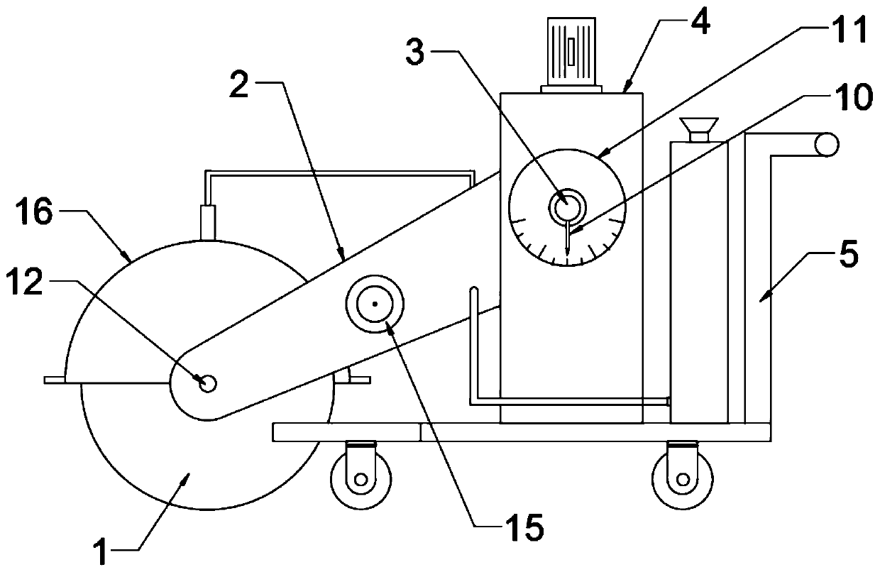
[0022] see Figure 1-5 , in an embodiment of the present invention, a bridge road precision slitting device includes a cutting wheel 1 and a cart 5; the cutting wheel 1 is rotatably connected to a swing arm 2 through a wheel shaft 12, and the swing arm 2 is rotatably connected to a rotating shaft 3 The support plate 4 is fixedly connected to the bottom plate of the cart 5; the axle 12 is connected to the output shaft 14 of the drive motor 15 through the first transmission belt 13, and the drive motor 15 is fixedly connected to the outer wall of the swing arm 2 by means of bolts , the output shaft 14 extends into the swing arm 2, and the first transmission belt 13 is nested in the swing arm 2 to prevent dust from polluting the transmission parts; the drive motor 15 is connected in series with the vehicle power supply and the motor switch through wires, and the vehicle power supply Fixedly connected with the bottom plate of the cart 5, the motor switch is fixedly connected with ...

Embodiment 2

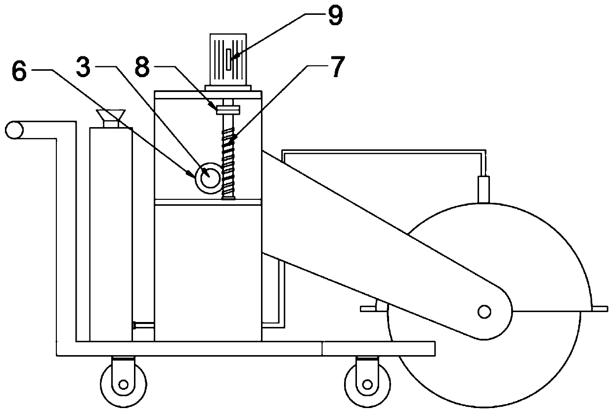
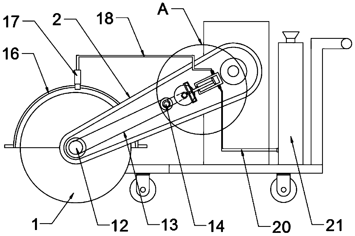
[0025] The difference between this embodiment and Embodiment 1 is that in order to reduce the volume of the device, the front end of the bottom plate of the trolley 5 is provided with a through groove, which facilitates the nesting of the swing arm 2 in the through groove and reduces the lateral length of the device; at the same time, A synchronous water spray mechanism is nested in the swing arm 2; the synchronous water spray mechanism includes a water pump 19, and the water pump 19 is nested in the swing arm 2 and is fixedly connected with the inner wall of the swing arm 2; The shell 16 and the top of the protective shell 16 are pierced with a nozzle 17, the nozzle 17 is connected to the water pump 19 through the water inlet pipe 18, and a first one-way valve is provided at the connection between the water inlet pipe 18 and the water pump 19, and the first one-way valve prevents water backflow Water cylinder 19; said water pump 19 communicates with a water tank 21 through a w...


PUM


Abstract

The invention discloses an accurate joint cutting device for a bridge road. The accurate joint cutting device comprises a cutting wheel and a cart. The cutting wheel is rotationally connected with a swing arm through a wheel shaft, the swing arm is rotationally connected with a supporting plate through a rotating shaft, and the supporting plate is fixedly connected with a bottom plate of the cart.The rear end of the rotating shaft extends to the rear side of the supporting plate, the rear end of the rotating shaft is fixedly connected with a worm gear, the worm gear is meshed with a worm, theworm is connected with a stepping motor through a coupler, the front end of the rotating shaft is fixedly connected with a pointer, and a dial is arranged on the inner side of the pointer. By arranging the swing arm, the rotating shaft, the worm wheel, the worm, the pointer and the dial, the height of the cutting wheel is accurately and visually adjusted, so that the joint cutting depth is accurately controlled, and the construction quality is improved; through the synchronous water spraying mechanism integrated in the swing arm and the cart bottom plate with the through groove in the front end, the overall size of the device is reduced, the driving structure of the device is simplified, movement and construction of the device are facilitated, and dust pollution is avoided.

Description

technical field [0001] The invention relates to the field of bridge road surface construction equipment, in particular to a bridge road precision cutting device. Background technique [0002] In the bridge pavement construction project, it is necessary to slit the road surface, retain the expansion joints, and prevent thermal expansion and contraction; the traditional slit device does not have a precise socket structure, and manual experience is required to control the depth of the slit, which is bulky and inconvenient to move. Not convenient for transportation. [0003] The present application provides a precise cutting device for bridge roads. Contents of the invention [0004] The object of the present invention is to provide a device for accurately cutting bridges and roads to solve the problems raised in the above-mentioned background technology. [0005] To achieve the above object, the present invention provides the following technical solutions: [0006] A devic...

Claims


Application Information

Patent Timeline
Patent Type & Authority Applications(China)
IPC IPC(8): E01C23/09
CPCE01C23/0933E01C2301/50
Inventor 王敏帆
Owner 王敏帆
Why Eureka
Try Eureka