Compaction vibration system for high-rise building foundation

A technology for high-rise buildings and vibration systems, applied in construction, soil protection, infrastructure engineering and other directions, can solve problems such as the inability to guarantee the safety of building foundations, poor performance, uneven compaction, etc. Short consumption time, good compaction effect

Inactive Publication Date: 2020-04-03
河南裕鸿建筑工程有限公司
View PDF6 Cites 2 Cited by
  • Summary
  • Abstract
  • Description
  • Claims
  • Application Information

AI Technical Summary

Problems solved by technology

[0006] The object of the present invention is to provide a kind of compaction vibration system of high-rise building foundation, to solve the uneven compaction of the existing building foundation proposed in the above-mentioned background technology, the effect is relatively poor, can not guarantee the safety, stability and safety of the building foundation. Technical issues such as lifespan

Method used


Image

  • Compaction vibration system for high-rise building foundation
  • Compaction vibration system for high-rise building foundation
  • Compaction vibration system for high-rise building foundation

Examples


Embodiment 1

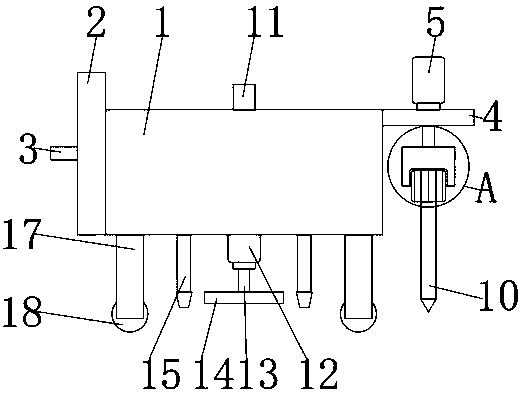
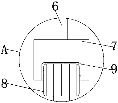
[0038] Such as Figure 1-4 As shown, a compaction vibration system for a high-rise building foundation includes a body 1, one side of the body 1 is fixedly connected with a first fixed plate 2, the inner bottom wall of the body 1 is provided with a through hole, and a part of the first fixed plate 2 The push handle 3 is fixedly connected to the middle part of the side, the second fixed plate 4 is fixedly connected to the top of the other side of the body 1, the top of the second fixed plate 4 is fixedly connected to the first hydraulic cylinder 5, and the bottom end of the first hydraulic cylinder 5 is fixedly connected to There is a first piston rod 6, and the bottom end of the first piston rod 6 is fixedly connected with a fixed block 7, and the bottom end of the first piston rod 6 passes through the second fixed plate 4 and is fixedly connected with the top of the fixed block 7. The bottom is provided with a groove, and the bottom of the fixed block 7 is fixedly connected w...

Embodiment 2

[0045] A compaction vibration system for the foundation of a high-rise building, comprising a body 1, one side of the body 1 is fixedly connected with a first fixing plate 2, the inner bottom wall of the body 1 is provided with a through hole, and the middle part of one side of the first fixing plate 2 is fixed The push handle 3 is connected, the top of the other side of the body 1 is fixedly connected with the second fixed plate 4, the top of the second fixed plate 4 is fixedly connected with the first hydraulic cylinder 5, and the bottom end of the first hydraulic cylinder 5 is fixedly connected with the first hydraulic cylinder 5. Piston rod 6, the bottom end of first piston rod 6 is fixedly connected with fixed block 7, and the bottom end of first piston rod 6 runs through second fixed plate 4 and is fixedly connected with the top of fixed block 7, and the bottom of fixed block 7 is provided with Groove, the bottom of fixed block 7 is fixedly connected with vibrating motor ...


PUM


Abstract

The invention discloses a compaction vibration system for a high-rise building foundation. The compaction vibration system comprises a machine body, wherein one side of the machine body is connected with a first fixing plate; a pushing handle is arranged in the middle of one side of the first fixing plate; the top of the other side of the machine body is connected with a second fixing plate; and the top of the second fixing plate is connected with a first hydraulic cylinder. According to the compaction vibration system for the high-rise building foundation, gravel soil, sandy soil, silt and the like below the foundation can be evenly distributed conveniently, and therefore the compaction effect is better, the sunken position of the ground can be filled conveniently, and the ground is keptflat; and the filling consumption time is short, few personnel are used, and therefore the labor cost is reduced.

Description

technical field [0001] The invention relates to the technical field of construction machinery for buildings, in particular to a compaction vibration system for high-rise building foundations. Background technique [0002] During building construction, the building foundation determines the safety, stability and life of the building to a large extent. Therefore, it is very important to build a solid foundation during building construction. [0003] All foundations used in buildings need to be compacted, especially for high-rise buildings. If the foundation is not fully compacted, it will cause depressions in the later construction ground, and in severe cases, it will cause the building to collapse and affect safety. The foundation is generally made of rocks, gravel soil, sandy soil, silt soil, cohesive soil, etc., backfilled with stone chip cushions, sand cushions, and mixed lime soil, and then compacted. [0004] However, in the prior art, the compaction of the building fo...

Claims


Application Information

Patent Timeline
Patent Type & Authority Applications(China)
IPC IPC(8): E02D3/046E02D3/054E02F5/22
CPCE02D3/046E02D3/054E02F5/226
Inventor 吴桂昌刘富明李朝磊王跃力李钢娄磊李冬玲周红曹玉虎苏悦潘梓鑫陈璞陈博晁会军潘文华徐小全耿雪
Owner 河南裕鸿建筑工程有限公司
Why Eureka
Try Eureka