Mechanical hydraulic compound transmission device and control method

A technology of hydraulic transmission and composite transmission, applied in transmission control, transmission, fluid transmission, etc., can solve the problems of reducing transmission efficiency, selecting less gears, and being difficult to take into account each other, so as to improve transmission efficiency and avoid circulating power. , the effect of optimizing the structural parameters

Active Publication Date: 2020-04-03
JIANGSU UNIV
View PDF8 Cites 21 Cited by
  • Summary
  • Abstract
  • Description
  • Claims
  • Application Information

AI Technical Summary

Problems solved by technology

At present, the design idea of ​​mechanical-hydraulic transmission is to sacrifice the transmission efficiency and speed regulation range of the secondary working area in exchange for the high-efficiency transmission of the main working area. The traditional design idea is difficult to take into account various working conditions including direction change and mode switching. Transmission needs
[0004] When the traditional transmission device realizes forward transmission and reverse transmission, the structure of power splitting and power converging is single, and it is difficult to take into account each other, which is not conducive to optimizing the structural parameters, and it is easy to generate circulating power, which reduces the transmission efficiency
Transmission devices with multiple modes often have fewer gears to choose from within the mode, which cannot adapt to the operation requirements of complex working conditions

Method used


Image

  • Mechanical hydraulic compound transmission device and control method
  • Mechanical hydraulic compound transmission device and control method
  • Mechanical hydraulic compound transmission device and control method

Examples


Embodiment Construction

[0077] The present invention will be further described below in conjunction with accompanying drawing.

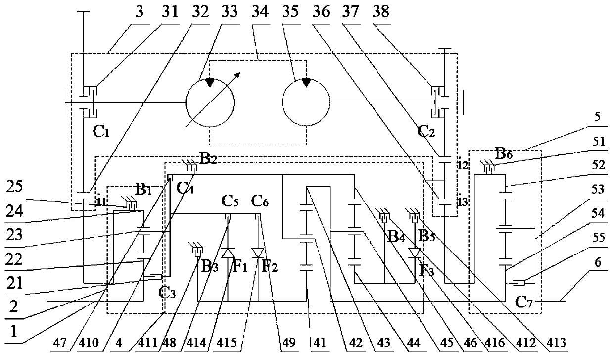
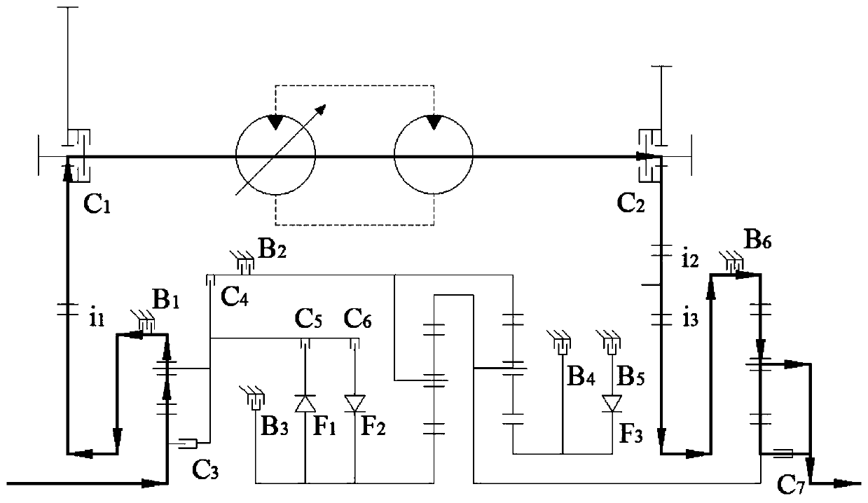
[0078] like figure 1 As shown, a mechanical-hydraulic compound transmission device includes an input shaft 1, a flow splitting mechanism 2, a hydraulic transmission assembly 3, a mechanical transmission assembly 4, a confluence mechanism 5 and an output shaft 6, and the input shaft 1 is connected in parallel with each other through the flow splitting mechanism 2. The hydraulic transmission assembly 3 is connected to the mechanical transmission assembly 4, and the hydraulic transmission assembly 3 and the mechanical transmission assembly 4 are respectively connected to the output shaft 6 through the flow converging mechanism 5; the flow diversion mechanism 2 includes a clutch C 3 21. The sun gear 22 of the diverter mechanism, the planet carrier 23 of the diverter mechanism, the ring gear 24 of the diverter mechanism and the brake B 1 25, the clutch C 3 21 are respectively ...


PUM


Abstract

The invention discloses a mechanical hydraulic compound transmission device and a control method. The mechanical hydraulic compound transmission device comprises an input shaft, a shunt mechanism, a hydraulic transmission assembly, a mechanical transmission assembly, a power dividing mechanism and an output shaft. The input shaft is connected with the hydraulic transmission assembly and the mechanical transmission assembly through the power dividing mechanism, and the hydraulic transmission assembly and the mechanical transmission assembly are connected in parallel. The hydraulic transmissionassembly and the mechanical transmission assembly are connected with the output shaft through the power dividing mechanism. The mechanical hydraulic compound transmission device has the beneficial effects that through combination of switching between a planetary gear structure and a brake and switching between the planetary gear structure and a clutch, the structural forms of power dividing and power gathering are realized; when forward transmission and reverse transmission are realized, the structural forms of power dividing and power gathering are diversified and compatible, and structure parameters can be optimized; moreover, occurrence of power circulation is avoided, and the transmission efficiency is improved. The transmission device has multiple optional gear levels and can adapt tooperation requirements under complex conditions. Moreover, a one-way variable pump and a one-way constant displacement motor are adopted, and the production and maintenance cost is greatly reduced.

Description

technical field [0001] The invention relates to a transmission device and a control method thereof, and in particular provides a mechanical-hydraulic composite transmission device and a control method capable of taking into account power splitting and power converging of each power section. Background technique [0002] The operating environment of high-power engineering vehicles is harsh and the load changes frequently, which puts forward higher requirements on the adaptability of the transmission system, which requires the transmission device to adapt to different working conditions with different speeds and torques in a timely manner to ensure Vehicle performance and fuel economy. The hydraulic transmission can realize flexible starting, the mechanical hydraulic transmission can realize stepless speed regulation, and the mechanical transmission can realize high-efficiency variable speed, which can meet the requirements of starting, operation and transition conditions resp...

Claims


Application Information

Patent Timeline
Patent Type & Authority Applications(China)
IPC IPC(8): F16H47/04F16H59/44F16H61/02F16H59/36F16H59/52
CPCF16H47/04F16H61/0213F16H59/44F16H59/52F16H2061/0244F16H2061/0015F16H2059/366F16H2200/2071F16H2200/201F16H2200/0078F16H2037/0866F16H2200/2087F16H2037/0886B60K6/12F16H2200/2012F16H2200/2056F16H2200/2061Y02T10/62B60K6/365F16H2047/045F16H37/10F16H2037/101
Inventor 朱镇蔡英凤陈龙夏长高韩江义田翔孙晓东赖龙辉施德华袁朝春
Owner JIANGSU UNIV
Why Eureka
Try Eureka