Photonic crystal fiber directional coupler

A photonic crystal fiber, directional coupler technology, applied in the coupling of optical waveguides, cladding fibers, optical waveguides and other directions, can solve difficulties and other problems, and achieve the effects of mature production technology, stable performance and low polarization-related loss.

Inactive Publication Date: 2013-05-08
JIANGSU UNIV
View PDF1 Cites 5 Cited by
  • Summary
  • Abstract
  • Description
  • Claims
  • Application Information

AI Technical Summary

Problems solved by technology

However, directional couplers that divide the energy into three with this three-core structure are rarely reported.
The main reason is that it is difficult to achieve an energy ratio of 1:1:1 (4.7 dB) in the three cores in a relatively wide operating wavelength range

Method used


Image

  • Photonic crystal fiber directional coupler
  • Photonic crystal fiber directional coupler
  • Photonic crystal fiber directional coupler

Examples


Embodiment 1

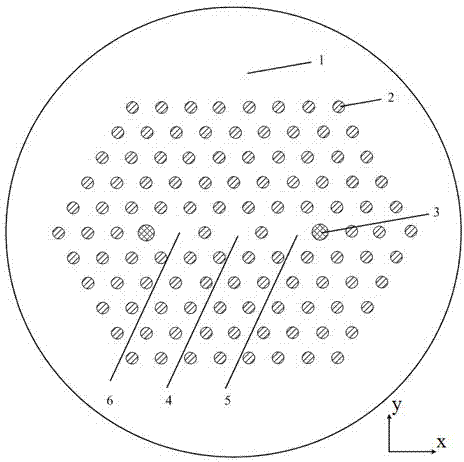
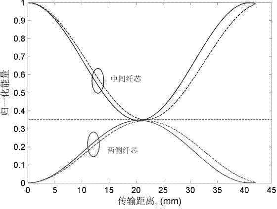
[0020] Its cross-section is as figure 1 As shown, the structural matrix material is quartz, the pore period Λ is 10 μm, the diameter of the first air hole 2 is 4.2 μm, and the diameter of the second air hole 3 is 4.8 μm. When the wavelength λ=1.55 μm, the coupling length of the x-polarization is calculated to be 20.4 cm, and the coupling length of the y-polarization is 21.4 cm. Take the average value (20.9 cm) of the coupling length of the two polarization directions as the length of the fiber coupler, and thus obtain the curve of the bandwidth of the coupler changing with the wavelength as follows: Figure 4 shown. It can be seen from the figure that when the insertion loss is within the range of 4.77±0.3 dB and the polarization-dependent loss is within the range of ±0.2 dB, its bandwidth is 127 nm.

[0021] Compared with the phase, the cross-section is taken as Figure 5 As shown, the structural matrix material is quartz, the pore period Λ is 10 μm, and the diame...


PUM


Abstract

The invention discloses a photonic crystal fiber directional coupler. Host material (1), holes (2) and holes (3) form fiber cores and a cladding, wherein the holes (2) and the holes (3) are formed in the host material (1). Centers of the holes (2) and the holes (3) are respectively located on nodes of a right triangle structured grid. The number of the fiber cores is three, where the first fiber core (4) is arranged on a center area of the host material (1), the right triangle structured grid misses a hole to from the first fiber core (4), the second fiber core (5) and the third fiber core (6) are symmetrically located on two sides of the first fiber core (4), the right triangle structured grid respectively misses a hole to from the fiber core (5) and the fiber core (6), air holes around innermost layers of the fiber core (5) and the fiber core (6) are the holes (2) and the holes (3), and the relationship of the diameter d2 of the holes (3) and the diameter d1 of the holes (2) satisfies that d2 >=d1. According to the photonic crystal fiber directional coupler, the diameters of the cladding air holes (3) of the fiber cores (the fiber core (5) and the fiber core (6)) on two sides are changed, and the advantages of being wide in wavelength coverage operation, insensitive to the fiber length and low in transmission loss and polarization relevant loss and other advantages are achieved.

Description

technical field [0001] The invention relates to the technical fields of optical fiber communication and sensing, and in particular to a photonic crystal fiber directional coupler. Background technique [0002] Optical fiber and optical waveguide directional coupler, as an important optical device, is widely used in optical fiber communication, cable TV network, subscriber loop system, area network and other systems. Although there are a variety of 1×2 beam splitting devices based on Y-shaped or T-shaped structures, due to their low transmittance, an additional fine-tuning structure needs to be introduced to improve the transmittance of the beam splitter, so as to give this type of light The manufacture of beam splitters poses difficulties. In recent years, with the introduction of photonic crystal fiber (PCF), especially because of its structural design flexibility and other characteristics, it has been widely studied. Photonic crystal fiber is a new type of optical wavegu...

Claims


Application Information

Patent Timeline
Patent Type & Authority Applications(China)
IPC IPC(8): G02B6/02G02B6/26
Inventor 陈明阳孙兵王涛钱春霖张永康
Owner JIANGSU UNIV
Why Eureka
Try Eureka