Equipment pipeline detection and control system based on LabVIEW

A pipeline detection and control system technology, applied in the pipeline system, mechanical equipment, electrical program control, etc., can solve the problems of lack of real-time alarm and automation, and achieve the effect of protecting the safety of the valve itself and enhancing flexibility

Pending Publication Date: 2020-04-03
RES INST OF PHYSICAL & CHEM ENG OF NUCLEAR IND
View PDF0 Cites 1 Cited by
  • Summary
  • Abstract
  • Description
  • Claims
  • Application Information

AI Technical Summary

Problems solved by technology

At present, the control process of this process is mainly to judge whether to manually open and close the valve manually through the on-site instrument reading, which has not realized automation, and does not have the function of real-time alarm for certain parameters.

Method used


Image

  • Equipment pipeline detection and control system based on LabVIEW
  • Equipment pipeline detection and control system based on LabVIEW
  • Equipment pipeline detection and control system based on LabVIEW

Examples


Embodiment 1

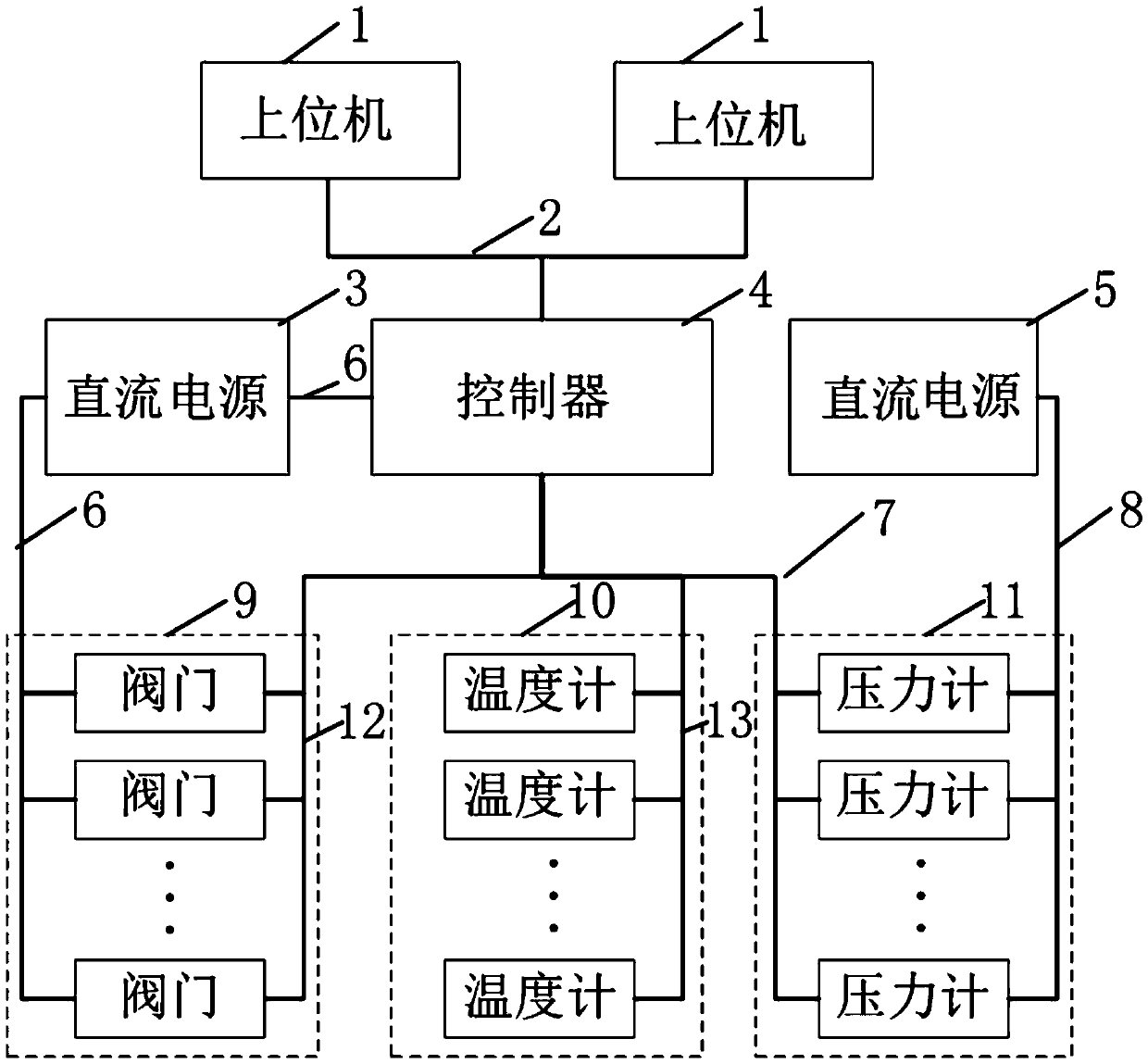
[0031] Such as figure 1 As shown, a LabVIEW-based equipment pipeline detection and control system includes at least one host computer 1, No. I DC power supply 3, controller 4, No. II DC power supply 5, valves 9, thermometers 10 and pressure gauges 11; Machine 1 is connected to controller 4, No. Ⅰ DC power supply 3 supplies power to controller 4 and valve 9, No. Ⅱ DC power supply 5 supplies power to pressure gauge 11; valve 9, thermometer 10 and pressure gauge 11 are respectively connected to controller 4 for electrical signals .

[0032] The upper computer 1 and the controller 4 are connected through an Ethernet cable 2, and the Ethernet cable 2 is a standard Ethernet twisted pair network cable.

[0033] The No. 1 DC power supply 3 provides DC 24V power supply for the controller 4 and the valve 9 through the power line 6, and the power line 6 is 2*1mm 2 cables.

[0034] The No. Ⅱ DC power supply 5 provides DC 24V power supply for the pressure gauge 11 through the shielded t...

Embodiment 2

[0046] Based on Embodiment 1, a method for equipment pipeline detection and control based on LabVIEW includes:

[0047] (I) data interaction between the controller 4 and the monitoring interface in the host computer 1;

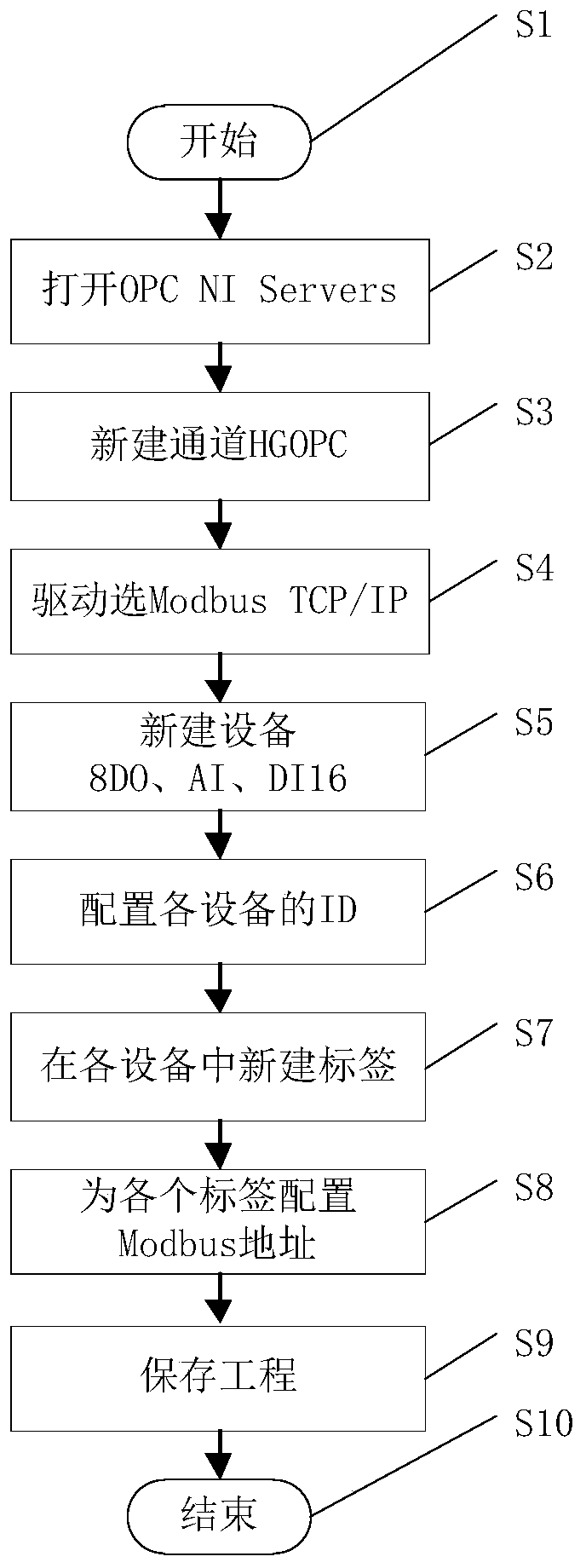
[0048] Such as figure 2 As shown, the real-time communication between the controller 4 and the upper computer 1 is realized through NI OPC Servers.

[0049] The data interaction between the controller 4 and the monitoring interface in the host computer 1 includes the following steps:

[0050] S1: start

[0051] S2: Open OPC NI Servers in NI of the start menu;

[0052] S3: Right-click the blank space, and name the new channel "HGOPC";

[0053] S4: Select Modbus TCP / IP Ethernet in the driver drop-down menu, keep clicking Next, and finally click "Finish";

[0054] S5: Create 3 new devices in the newly created channel "HGOPC" and name them "8DO", "AI" and "DI16" respectively;

[0055] S6: Configure the IDs of the newly created 3 devices;

[0056] S7: Creat...


PUM


Abstract

The invention discloses a equipment pipeline detection and control system based on LabVIEW. The equipment pipeline detection and control system comprises at least one upper computer, wherein the uppercomputer is connected with a controller, a first direct current power supply supplies power to the controller and valves, a second direct current power supply supplies power to pressure gauges, and the valves, thermometers and the pressure gauges are respectively in electrical signal connection with the controller. The system can display, store, query and export various process parameters in realtime, alarm the process parameters exceeding the alarm limit in real time, and does not output the alarm sound in the shielding state; by clicking different buttons, opening and closing of the valvescan be manually or automatically controlled, the whole process flow is guaranteed to be safe and smooth, and meanwhile, flexibility is enhanced; and when the valves are manually or automatically controlled, after the upper computer software receives opening and closing of the valves in place or 8s later, relays controlling the valves are released, motors of the valves are powered off, the safetyof the valves themselves can be protected, and the motors are prevented from being burnt out.

Description

technical field [0001] The invention belongs to the field of pipeline data acquisition and valve control, and in particular relates to a LabVIEW-based equipment pipeline detection and control system. Background technique [0002] When special equipment is performing a special process, it is necessary to collect various process parameters in real time, display them on the human-computer interaction interface, and have functions such as alarm, storage, and query; at the same time, in order to ensure the smooth progress of the entire process and The safety of the process pipeline needs to automatically control the opening and closing of certain valves. At present, the control process of this process is mainly to judge whether to manually open and close the valve manually through the instrument reading on site, which has not realized automation, and does not have the function of real-time alarm for certain parameters. Contents of the invention [0003] The present invention i...

Claims


Application Information

Patent Timeline
Patent Type & Authority Applications(China)
IPC IPC(8): F17D5/00F16K31/04G01D21/02G05B19/04
CPCF16K31/04F17D5/00G01D21/02G05B19/04
Inventor 李志东孙睿李义祥谢隽兰鹏钱世玺
Owner RES INST OF PHYSICAL & CHEM ENG OF NUCLEAR IND
Why Eureka
Try Eureka