
Temperature and humidity transmitter protection device

A technology for protection devices and transmitters, applied in the direction of measuring devices, measuring device casings, instruments, etc., can solve the problems of no protective design, acceleration of rain and dust, corrosion, etc., to reduce corrosion, reduce the probability of air ingress, and improve The effect of thermal conductivity

Inactive Publication Date: 2020-04-03
西安致开工业自动化工程有限公司
View PDF2 Cites 1 Cited by
  • Summary
  • Abstract
  • Description
  • Claims
  • Application Information

AI Technical Summary

Problems solved by technology

[0004] The purpose of the present invention is to provide a temperature and humidity transmitter protection device to solve the problem of no protection design, rain and dust accelerated corrosion in the above background technology

Method used


Image

  • Temperature and humidity transmitter protection device
  • Temperature and humidity transmitter protection device
  • Temperature and humidity transmitter protection device

Examples


Embodiment 1

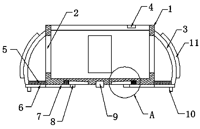
[0023] like figure 1 As shown, it includes a protective casing 1, the side wall of the protective casing 1 is equidistantly excavated with a plurality of through grooves 2, and a protective box 3 is fixedly connected to the position of the side wall of the protective casing 1 and the positions of the plurality of through grooves 2. The outer side wall is fixedly connected with a plurality of heat sinks 11 at equal distances, and the bottom end of the protective box 3 is fixedly connected with a protective net 5. The protective box 3 can shield and protect the through groove 2 of the protective shell 1, which greatly reduces the fall of dust and rainwater. The probability of protecting the inside of the casing 1 is to protect the temperature and humidity transmitter inside. At the same time, the plurality of heat sinks 11 can improve the heat conduction efficiency and enhance the heat dissipation inside the protective casing 1 .

Embodiment 2

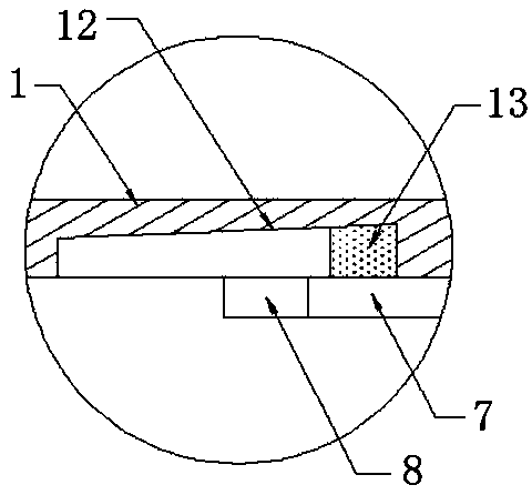
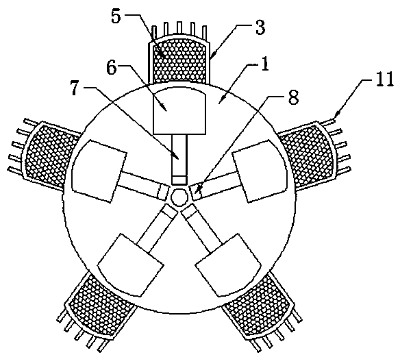
[0025] On the basis of Example 1, as figure 2 and image 3 As shown, an electromagnet 9 is fixedly connected to the center of the bottom end of the protective casing 1, and a humidity switch 4 is fixedly embedded on one side of the top end of the protective casing 1. The electromagnet 9 is electrically connected to the power supply through the humidity switch 4, and the bottom of the protective casing 1 is There are a plurality of slideways 12 equidistantly excavated at the ends, and the plurality of slideways 12 are at an angle of 5-20 degrees with the horizontal plane. The interiors of the plurality of slideways 12 are slidably connected with sliders 13, and the bottom ends of the plurality of sliders 13 are all slidably connected. A connecting rod 7 is fixedly connected, one end of the plurality of connecting rods 7 is fixedly connected with a magnetic block 8, the other end of the plurality of connecting rods 7 is fixedly connected with a blocking plate 6, and one side of...


PUM


Abstract

The invention discloses a temperature and humidity transmitter protection device. The device comprises a protective shell. A plurality of through grooves are equidistantly dug in the side wall of theprotective shell; protective boxes are fixedly connected to the positions, corresponding to the through grooves, of the side wall of the protective shell. A plurality of cooling fins are fixedly connected to the outer side wall of the protection box at equal intervals; the bottom end of the protection box is fixedly connected with a protection net; an electromagnet is fixedly connected to the center of the bottom end of the protective shell; a humidity switch is fixedly embedded in one side of the top end of the protective shell; the electromagnet is electrically connected with a power supplythrough a humidity switch; a plurality of slideways are dug in the bottom end of the protective shell at equal intervals; according to the temperature and humidity transmitter protection device, the protection box is arranged, shielding protection can be conducted on the through groove of the protection shell under the condition that the protection box is used in cooperation with the multiple cooling fins, the probability that dust and rainwater fall into the protection shell is greatly reduced. Meanwhile, the heat conduction efficiency is improved, and the heat dissipation performance in theprotection shell is enhanced.

Description

technical field [0001] The invention relates to a protection device, in particular to a temperature and humidity transmitter protection device. Background technique [0002] In air handling equipment, the temperature and humidity transmitter is a kind of temperature and humidity transmitter equipped with humidity-sensitive and temperature-sensitive components, together with an integrated processing circuit, so as to convert the temperature and relative humidity in the environment into corresponding standard analog signals. , a transmitter device that measures and displays air temperature and humidity. [0003] In response to this, Chinese Patent No. CN202485703U proposes a humidity temperature transmitter protection device, which is sleeved on the probe of the humidity temperature transmitter through the humidity temperature transmitter protective sleeve, which reduces the failure rate of the temperature and humidity transmitter; China Patent No. CN209372110U proposes an an...

Claims


Application Information

Patent Timeline
Patent Type & Authority Applications(China)
IPC IPC(8): G01D11/24
CPCG01D11/245
Inventor 白琳
Owner 西安致开工业自动化工程有限公司
Features
  • Generate Ideas
  • Intellectual Property
  • Life Sciences
  • Materials
  • Tech Scout
  • Unparalleled Data Quality
  • Higher Quality Content
  • 60% Fewer Hallucinations
Learn More