Test device for simulating multidirectional coupling cyclic loading of anchor pile system

A test device, cyclic loading technology, applied in the direction of measuring device, using repeated force/pulsation force to test the strength of materials, instruments, etc., can solve the problem that cyclic loading can only be carried out in a single horizontal or vertical direction, and the marine environment cannot be truly simulated Problems such as the force condition of the medium foundation and narrow application range achieve the effects of wide application range, increased adjustment range, and improved measurement accuracy

Active Publication Date: 2020-04-03
TONGJI UNIV
View PDF8 Cites 6 Cited by
  • Summary
  • Abstract
  • Description
  • Claims
  • Application Information

AI Technical Summary

Problems solved by technology

Referring to the foundation forms of fixed offshore wind turbines and offshore oil exploration platforms, LeBlanc et al. (2010) and Muhanmad et al. (2016) developed two different long-term horizontal cyclic loading devices for single piles, and Yeong-Hoon et al. (2017) developed a suction bucket The vertical long-term vertical cyclic loading equipment of the mooring foundation, but the above equipment can only be cyclically loaded in a single horizontal or vertical direction. The anchor pile foundation bears the coupled cyclic load of vertical buoyancy and horizontal wave force, and loading in a single direction cannot Realistically simulate the stress of the foundation in the marine environment
Moreover, the two types of devices can only carry out specific tests, which have poor versatility and narrow scope of application.

Method used


Image

  • Test device for simulating multidirectional coupling cyclic loading of anchor pile system
  • Test device for simulating multidirectional coupling cyclic loading of anchor pile system
  • Test device for simulating multidirectional coupling cyclic loading of anchor pile system

Examples


Embodiment Construction

[0033] The following will clearly and completely describe the technical solutions in the embodiments of the present invention with reference to the drawings in the embodiments of the present invention. Obviously, the described embodiments are part of the embodiments of the present invention, not all of them. Based on the embodiments of the present invention, all other embodiments obtained by persons of ordinary skill in the art without making creative efforts shall fall within the protection scope of the present invention.

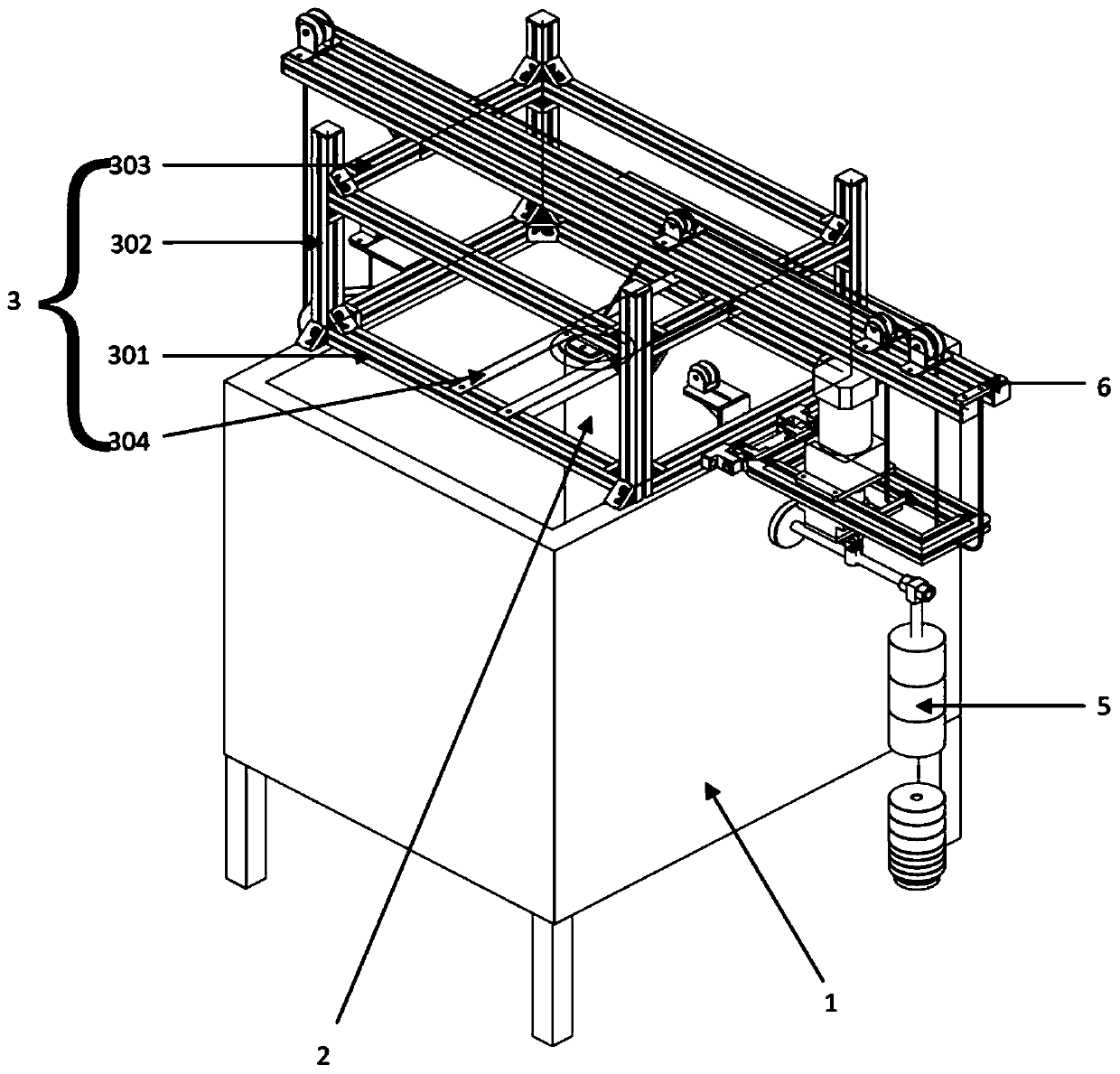
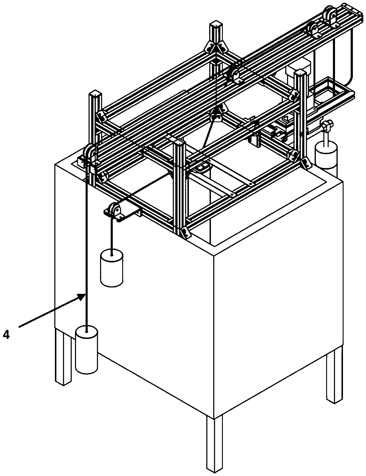
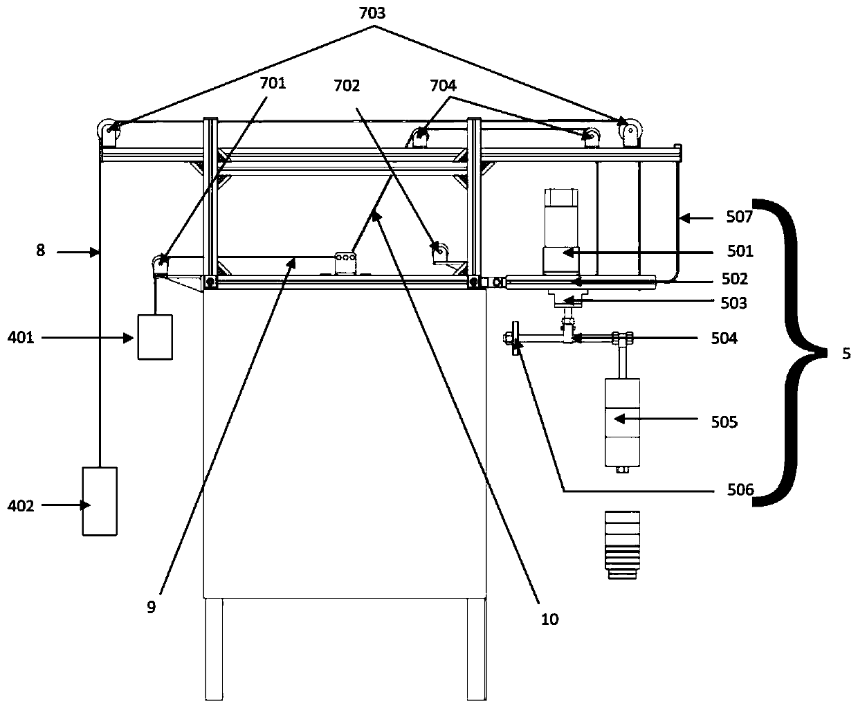
[0034] The invention relates to a test device for simulating multidirectional coupled cyclic loading of anchor pile systems, such as Figure 1-4 As shown, it includes model box 1, model pile 2, reaction frame 3, static balance unit 4, power circulation unit 5, diameter guide rail 6, pulley 7, balance weight cable 8, horizontal loading cable 9 and oblique loading cable 10.

[0035] Model box 1 is provided with soil, the soil in this embodiment is sandy soi...


PUM

PropertyMeasurementUnit
lengthaaaaaaaaaa
widthaaaaaaaaaa
heightaaaaaaaaaa

Abstract

The invention relates to a test device for simulating multidirectional coupling cyclic loading of an anchor pile system. The test device comprises a model pile buried in a model box, a reaction frame,a static balance unit, a power circulation unit, a diameter guide rail, a balance weight pull wire, a horizontal loading pull wire and an oblique loading pull wire. The balance weight pull wire is connected with the power circulation unit to balance the gravity of the power circulation unit and is connected with the model pile to provide a vertical static load or an oblique static load for the model pile, the static balance unit is also connected with the model pile through a horizontal loading pull wire to provide a horizontal load for the model pile, and the power circulation unit is connected with the model pile through the oblique loading pull wire to provide circulation loads for the model pile. Compared with the prior art, the test device has the advantages of wide application range, high simulation precision, small size and the like.

Description

technical field [0001] The invention relates to a static and dynamic cyclic loading device in a model test, in particular to a test device for simulating multidirectional coupled cyclic loading of an anchor pile system. Background technique [0002] In recent years, in the face of increasingly severe environmental and resource problems, countries around the world are seeking safer, cleaner and renewable energy. In my country's energy consumption, traditional fossil energy accounts for a large proportion, with low energy utilization efficiency, large waste and pollution, so it is particularly urgent to develop new clean energy. In the past two decades, wind turbines have developed rapidly all over the world. China has become the country with the largest installed wind power capacity in the world. The construction of offshore wind power projects can make full use of abundant wind energy resources. Wind power projects have developed from land to shallow seas, and from shallow ...

Claims


Application Information

Patent Timeline
Patent Type & Authority Applications(China)
IPC IPC(8): G01N3/34
CPCG01N3/34G01N2203/0005G01N2203/0017G01N2203/0033G01N2203/0682
Inventor 黄茂松俞剑潘志杰
Owner TONGJI UNIV
Why Eureka
Try Eureka