
Cutting simulation implementation method for real-time machining monitoring

A technology of real-time monitoring and realization method, applied in the direction of design optimization/simulation, geometric CAD, etc., can solve the problems of incompatible interfaces of the built-in control system, inconvenient preset trajectory of cutting process parameters, etc., and achieve wide application range and optimization Real-time simulation speed and precision control, the effect of meeting individual needs

Pending Publication Date: 2020-04-03
SHANGHAI JIAO TONG UNIV
View PDF0 Cites 5 Cited by
  • Summary
  • Abstract
  • Description
  • Claims
  • Application Information

AI Technical Summary

Problems solved by technology

[0002] Cutting simulation technology is an important part of the simulation optimization technology of the manufacturing process. Compared with the conventional cutting simulation algorithm, the cutting simulation technology for real-time monitoring of processing puts forward more requirements: first, the real-time cutting algorithm needs to have faster Calculate the speed to achieve synchronous display with the actual processing process; secondly, in actual production, the intelligent process of the manufacturing workshop is usually not completed in one step, but is gradually upgraded on the basis of the existing manufacturing equipment. Considering the existing manufacturing equipment of the factory There are many types of cutting equipment, and the compatibility of the interface of the built-in control system is different. It is not convenient to share the preset cutting process parameters, such as the preset trajectory of the tool. This requires the cutting algorithm to be able to complete the simulation without the predetermined cutting process parameters. calculate

Method used


Image

  • Cutting simulation implementation method for real-time machining monitoring
  • Cutting simulation implementation method for real-time machining monitoring
  • Cutting simulation implementation method for real-time machining monitoring

Examples


Embodiment Construction

[0045] This embodiment specifically includes the following steps:

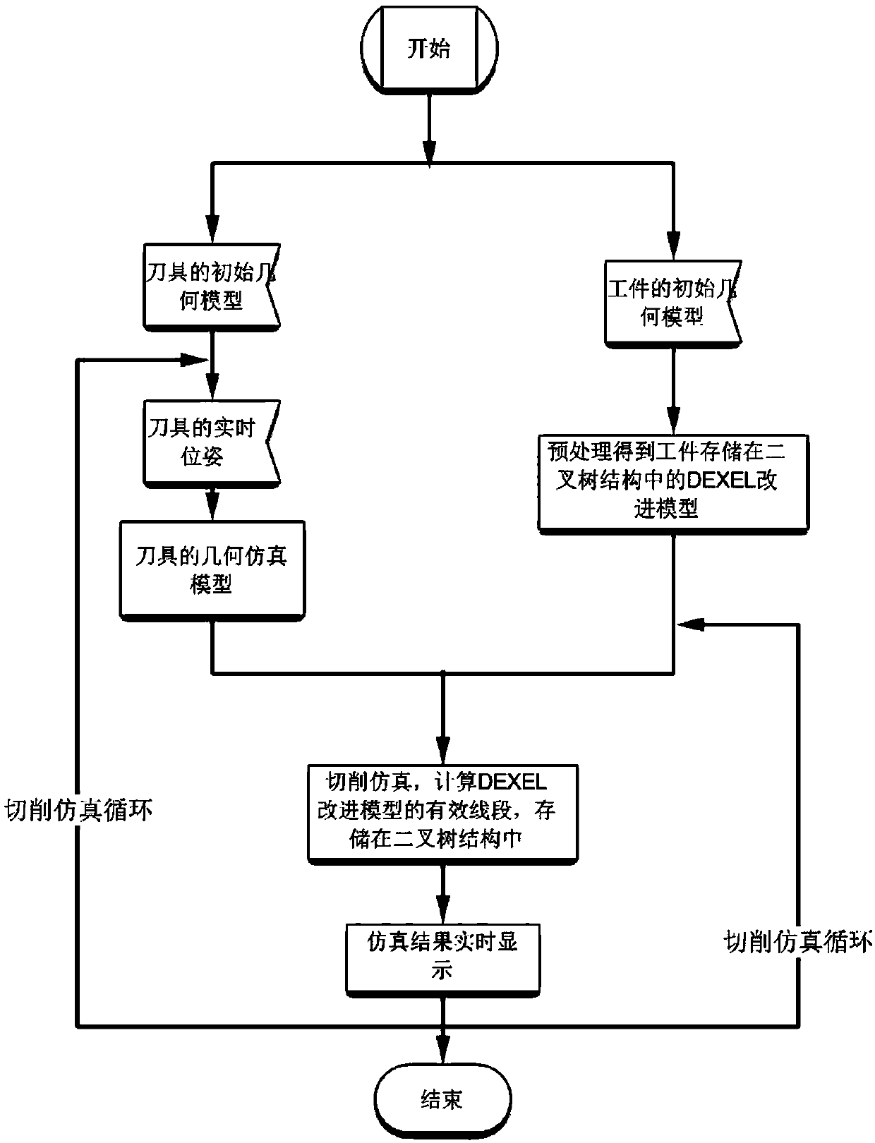
[0046] Step 1. Establishing a geometric simulation model of the tool, specifically: using a collection of multiple isolated tool poses with very short time or pose intervals to approximate the enveloping body of the replacement tool. During the simulation process, when the initial geometric model of the tool and the real-time sensing information of the tool pose are known, the geometric simulation model of the tool for each isolated cutting pose can be simulated and calculated.

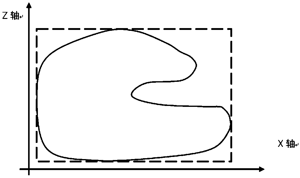
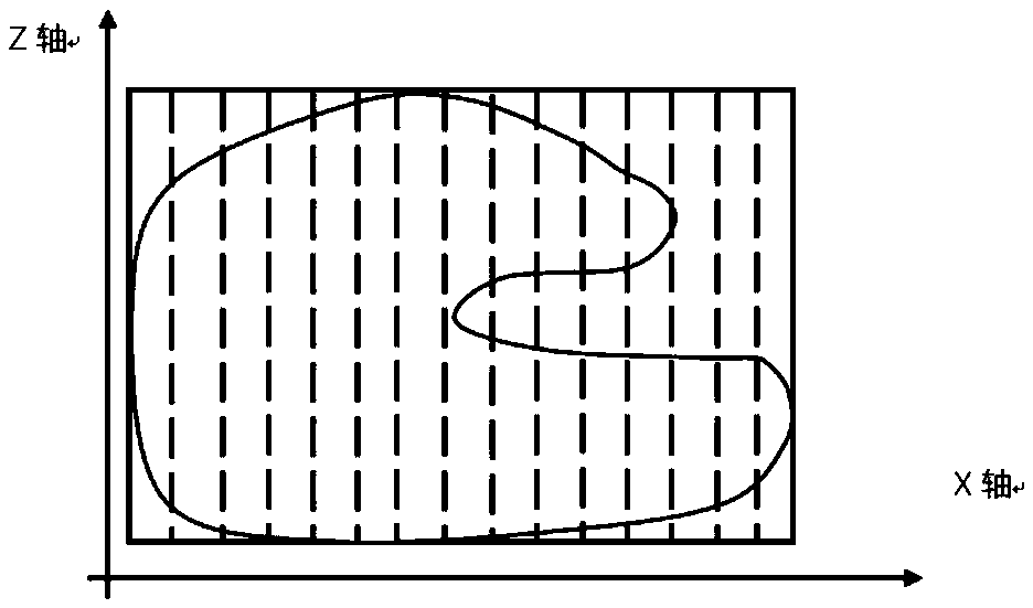
[0047] Step 2. While performing step 1, perform DEXEL improved model preprocessing on the workpiece to obtain the DEXEL improved model of the workpiece; the modeling method of the one-way DEXEL improved model is also applicable to the two-way and three-way DEXEL improved models, The latter generalizes the Z-direction unidirectional DEXEL ray group on the XOY plane to a mutually perpendicular two-direction DEXEL ray group and a mutuall...


PUM


Abstract

The invention discloses a cutting simulation implementation method for real-time machining monitoring. The method includes: firstly, establishing a geometric simulation model of a cutter for the cutter; establishing a DEXEL improved model of a workpiece for the workpiece, performing cutting simulation operation by using a geometric simulation model of a cutter and the DEXEL improved model of the workpiece to obtain an updated DEXEL improved model of the workpiece, and finally constructing the updated DEXEL improved model into a triangular patch display model to realize real-time display. According to the method, a data storage and search structure of a Depth Element, Dexel real-time modeling algorithm and a geometric simulation model of a cutter are optimized, the simulation speed of the numerical control cutting (including turning and milling) real-time simulation process is increased, and cutting simulation oriented to real-time machining monitoring is achieved.

Description

technical field [0001] The invention relates to a technology in the field of mechanical processing, in particular to a cutting simulation realization method oriented to real-time monitoring of processing. Background technique [0002] Cutting simulation technology is an important part of the simulation optimization technology of the manufacturing process. Compared with the conventional cutting simulation algorithm, the cutting simulation technology for real-time monitoring of processing puts forward more requirements: first, the real-time cutting algorithm needs to have faster Calculate the speed to achieve synchronous display with the actual processing process; secondly, in actual production, the intelligent process of the manufacturing workshop is usually not completed in one step, but is gradually upgraded on the basis of the existing manufacturing equipment. Considering the existing manufacturing equipment of the factory There are many types of cutting equipment, and the...

Claims


Application Information

Patent Timeline
IPC IPC(8): G06F30/17G06F30/20
Inventor 武殿梁曹玉娟
Owner SHANGHAI JIAO TONG UNIV
Learn More