
Optical comb control method and system based on electric control polarization controller

A technology of polarization controller and control system, applied in the field of laser, which can solve problems such as inconvenient locking

Inactive Publication Date: 2020-04-03
CHONGQING INST OF EAST CHINA NORMAL UNIV +1
View PDF5 Cites 2 Cited by
  • Summary
  • Abstract
  • Description
  • Claims
  • Application Information

AI Technical Summary

Problems solved by technology

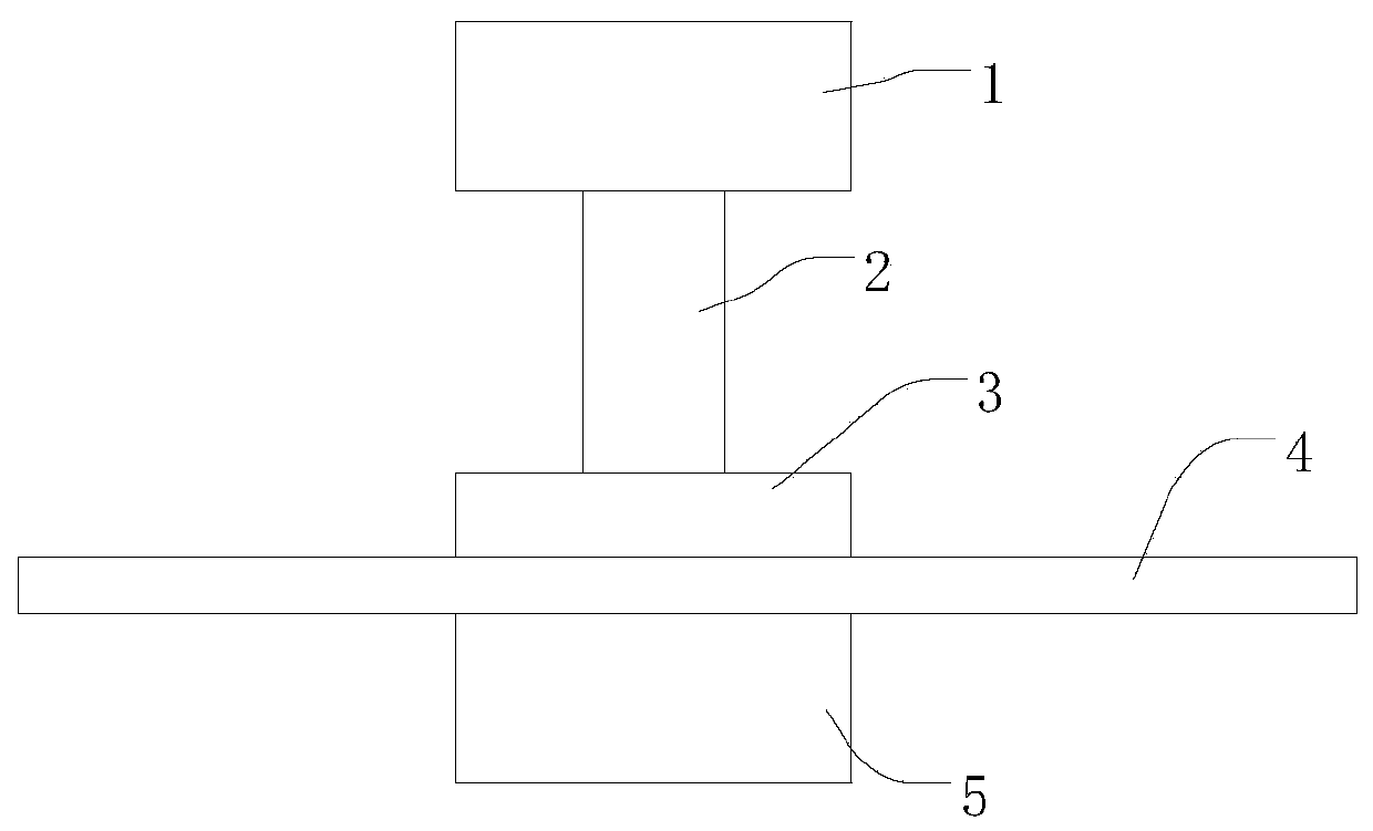
[0005] In view of the above-mentioned shortcoming of the prior art, the object of the present invention is to provide a kind of optical comb control method and system based on the electronically controlled polarization controller, for solving the inconvenient locking f in the prior art r with f 0 signal problem

Method used


Image

  • Optical comb control method and system based on electric control polarization controller
  • Optical comb control method and system based on electric control polarization controller
  • Optical comb control method and system based on electric control polarization controller

Examples


Embodiment Construction

[0046] Embodiments of the present invention are described below through specific examples, and those skilled in the art can easily understand other advantages and effects of the present invention from the content disclosed in this specification. The present invention can also be implemented or applied through other different specific embodiments, and the details in this specification can also be modified or changed based on different viewpoints and applications without departing from the spirit of the present invention.

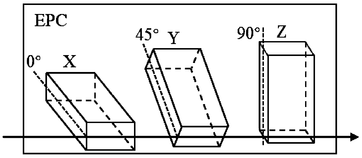
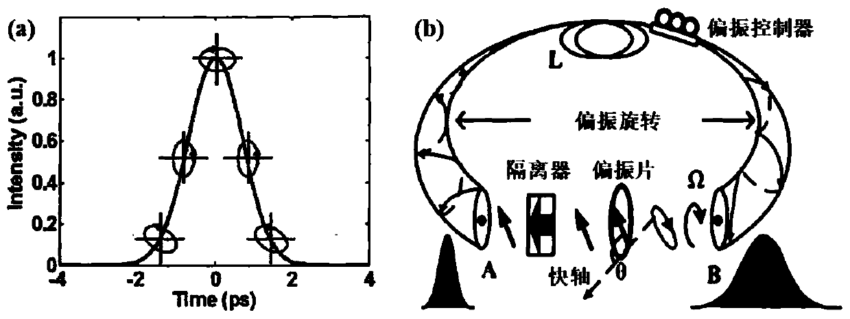
[0047] see Figure 1 to Figure 10 . It should be noted that the diagrams provided in this embodiment are only schematically illustrating the basic idea of ​​the present invention, and only the components related to the present invention are shown in the diagrams rather than the number, shape and shape of the components in actual implementation. Dimensional drawing, the type, quantity and proportion of each component can be changed arbitrarily during actual i...


PUM


Abstract

The invention provides an optical comb control method and system based on an electric control polarization controller. The system comprises a laser light source used for providing seed light, an amplifying device used for amplifying the energy of the seed light, a self-reference beat frequency detection device used for detecting and obtaining a repetition frequency signal and a carrier envelope phase signal, and a phase locking device used for locking the repetition frequency signal and the carrier envelope phase signal. The polarization state of the seed light in the optical fiber is controlled by applying a driving voltage through the electric control polarizer and the module, and nonlinear polarization rotation of the seed light is realized; locking of the carrier envelope phase signalis realized by controlling the polarization state of the seed light in the resonant cavity; phase locking of repetition frequency signals is achieved by controlling the length of the resonant cavity.

Description

technical field [0001] The invention relates to the field of lasers, in particular to an optical comb control method and system based on an electronically controlled polarization controller. Background technique [0002] Femtosecond fiber optical frequency comb, referred to as "optical comb", has become another major breakthrough in the field of laser technology after the advent of ultrashort pulse laser. Two scientists who have made outstanding contributions in this field, J.Hall and Shared half of the 2005 Nobel Prize in Physics. [0003] The main feature of the optical comb is that the frequency coverage is wide and the linewidth of a single spectral line is extremely narrow, which is equivalent to an ultra-fine "frequency ruler", which can increase the frequency measurement accuracy to 10 -19 , greatly accelerating the research progress in the fields of precision spectroscopy, quantum manipulation, optical clocks, and life sciences. From the point of view of mathemat...

Claims


Application Information

Patent Timeline
Patent Type & Authority Applications(China)
IPC IPC(8): H01S3/13H01S3/109H01S3/105H01S3/10
CPCH01S3/10061H01S3/10092H01S3/1053H01S3/109H01S3/1305H01S3/1307
Inventor 曾和平刘婷婷沈旭玲
Owner CHONGQING INST OF EAST CHINA NORMAL UNIV
Learn More