Atomizing nozzle for lift pipe of catalytic cracking device

A catalytic cracking device and atomizing nozzle technology, which is applied in catalytic cracking, cracking, chemical instruments and methods, etc., can solve the problem that nozzles cannot produce fine droplet spray patterns, shutdown and replacement costs are unfavorable, nozzles are difficult to obtain performance, etc. problem, to achieve the effect of cutting oil and gas molecules, improving the atomization effect, and good pressure

Inactive Publication Date: 2020-04-07
PETROCHINA CO LTD
View PDF10 Cites 0 Cited by
  • Summary
  • Abstract
  • Description
  • Claims
  • Application Information

AI Technical Summary

Problems solved by technology

This spray increases the area of ​​the raw material droplets, which is beneficial to the contact between the raw material droplets and the catalyst particles, however, the existing nozzles are difficult to obtain the desired performance
Some nozzles utilize very small openings or complex head designs, which are easily clogged by various impurities in the raw material. Downtime and replacement costs are very disadvantageous in the process of repairing such clogging. Existing nozzles cannot produce Fine droplets and / or ideal spray patterns

Method used


Image

  • Atomizing nozzle for lift pipe of catalytic cracking device
  • Atomizing nozzle for lift pipe of catalytic cracking device
  • Atomizing nozzle for lift pipe of catalytic cracking device

Examples


Embodiment 1

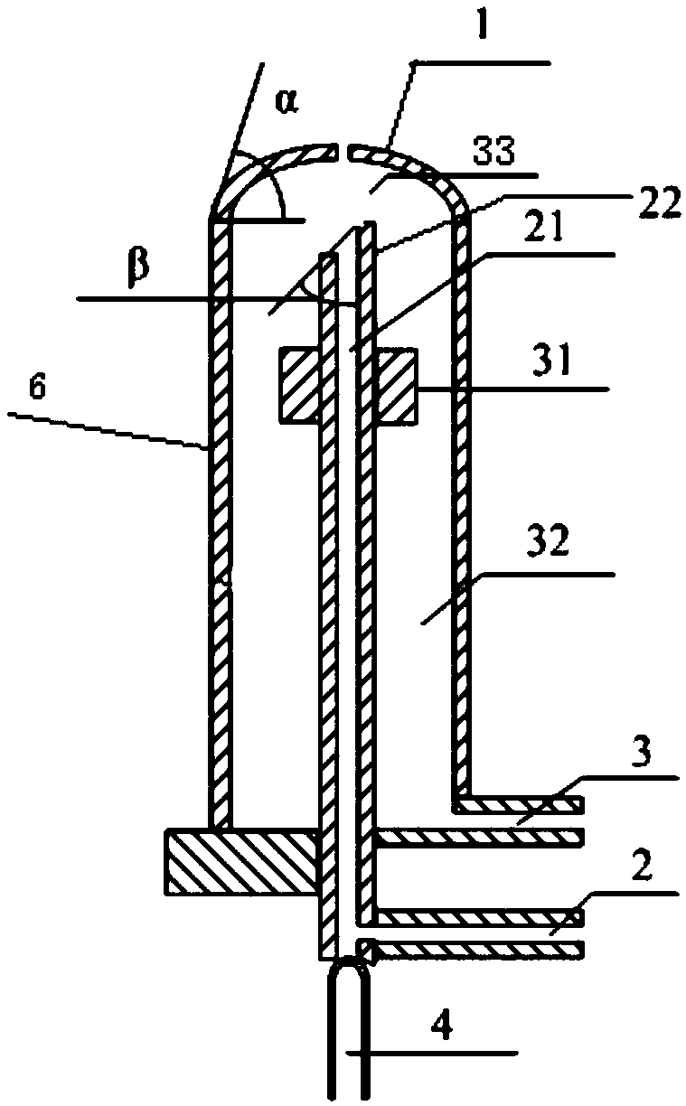
[0078] The atomizing nozzle for the riser of the catalytic cracking device adopted in this embodiment includes a nozzle main body, and the nozzle main body is a two-layer casing composed of an inner pipe 21 and an outer pipe 6, and the two ends of the two-layer casing are respectively It is an inlet port and an outlet port, the inlet port of the inner tube 21 is located outside the outer tube 6, and the outlet end of the inner tube 21 is located inside the outer tube 6;

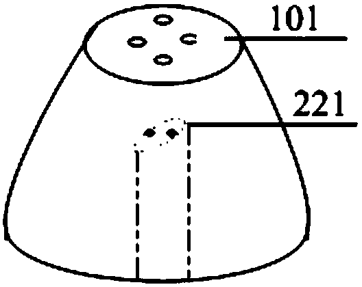
[0079]The outlet end of the outer tube 6 is provided with a second nozzle head 1, the second nozzle head 1 is a half-drum shape, the outlet end of the inner pipe 21 is provided with a first nozzle head 22, and the inlet end of the first nozzle head 22 is connected to the inner The outlet end of the pipe 21 is connected, the outlet end of the first nozzle head 22 is close to the outlet end of the second nozzle head 1, and the distance between the outlet end of the first nozzle head 22 and the outlet end of the ...


PUM


Abstract

The invention provides an atomizing nozzle for a lift pipe of a catalytic cracking device. The atomizing nozzle comprises a nozzle main body; the nozzle main body is a two-layer casing pipe composed of an inner pipe and an outer pipe, the two ends of the two-layer casing pipe are an inlet end and an outlet end respectively, the inlet end of the inner pipe is located outside the outer pipe, and theoutlet end of the inner pipe is located inside the outer pipe; a second nozzle head is arranged at the outlet end of the outer pipe, the inlet end of the second nozzle head is connected with the outlet end of the outer pipe, the outlet end of the second nozzle head extends towards the exterior of the outer pipe, the cross section area of the second nozzle head is gradually reduced in the direction away from the outer pipe, and the cross section of the second nozzle head is circular; a first nozzle head is arranged at the outlet end of the inner pipe and provided with at least one channel andat least one outlet end; at least one bulge is arranged on the outer wall of the inner pipe.

Description

technical field [0001] The invention relates to an atomizing nozzle, in particular to an atomizing nozzle for a riser of a catalytic cracking device. Background technique [0002] The task of the feed atomizing nozzle is to atomize the raw oil (heavy oil or residual oil or its mixture) and the re-refined oil of the catalytic cracking unit into fine droplets and spray them into the riser. At the temperature in the riser, the raw oil is vaporized and A cracking reaction occurs under the action of a catalyst, and then passes through a separation device to separate oil, gas and chemicals into the next process. [0003] General feed atomization nozzles are composed of a mixing chamber and a spray section. In the mixing chamber, the atomized liquid and the auxiliary atomized steam meet, shear and tear each other to form a two-phase flow mixed with each other, and then the two-phase flow is sprayed out through the nozzle of the discharge section. These nozzles basically use the f...

Claims


Application Information

Patent Timeline
IPC IPC(8): B01J8/24B01J8/38C10G11/05C10G11/18
CPCB01J8/388B01J8/245C10G11/05C10G11/182C10G11/18
Inventor 柳召永张忠东王艳飞刘涛杨朝阳刘明霞王辰晨汪毅樊红超翟佳宁孙志国杜晓辉
Owner PETROCHINA CO LTD
Why Eureka
Try Eureka