
Auxiliary calibration device and method for tail end pose of mechanical arm

A calibration device and pose calibration technology, applied to manipulators, program-controlled manipulators, manufacturing tools, etc., can solve the problems of high manipulator operation requirements, lack of universal applicability, and long time-consuming, and achieve low operation difficulty and calibration The effect of high efficiency and low cost

Active Publication Date: 2020-04-07
NANJING UNIV OF AERONAUTICS & ASTRONAUTICS
View PDF8 Cites 6 Cited by
  • Summary
  • Abstract
  • Description
  • Claims
  • Application Information

AI Technical Summary

Problems solved by technology

The traditional pose calibration method of the end of the manipulator is to control the visual equipment to keep still, drive the manipulator to move several positions, collect the spatial coordinate information of these positions, and then calibrate the end of the manipulator. Due to the vision-based positioning in the actual engineering environment It is necessary to track the manipulator in real time and guide and position it. Considering the visual range of the vision equipment, it is necessary to ensure that the vision equipment is in an active state. Because the traditional calibration method has high requirements for the operation of the manipulator arm, it is difficult and subject to Human factors are greatly affected and calibration takes a long time, so it is not universal

Method used


Image

  • Auxiliary calibration device and method for tail end pose of mechanical arm
  • Auxiliary calibration device and method for tail end pose of mechanical arm
  • Auxiliary calibration device and method for tail end pose of mechanical arm

Examples


Embodiment Construction

[0028] Embodiments of the present invention will be further described in detail below in conjunction with the accompanying drawings.

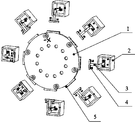
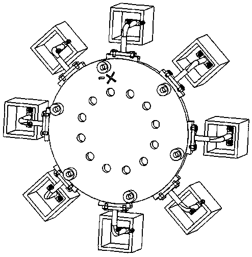
[0029]An auxiliary calibration device for the position and posture of the end of the mechanical arm in this embodiment is characterized in that it includes a flange 1, a calibration regular polyhedron 2 and a connecting rod 3, the center of the disk on one side of the flange 1 and the industrial mechanical arm The end effector is fixedly connected, and there are multiple calibration regular polyhedrons 2. The calibration regular polyhedron 2 is fixed on the outer side of the peripheral surface of the flange 1 through the connecting rod 3, except for the side connecting the calibration regular polyhedron 2 and the connecting rod 3, and the other surfaces Target paper is attached to each surface, and the codes of each target paper are different. The target paper is located within the visual range of the calibration vision equipment at the end of t...


PUM


Abstract

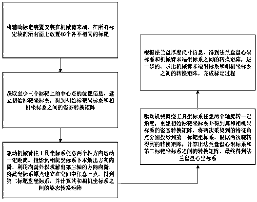
The invention discloses an auxiliary calibration device and method for the tail end pose of a mechanical arm and is used for rapidly calibrating the tail end pose of an industrial robot. The auxiliarycalibration device comprises a flange plate, a connecting rod and a calibration regular polyhedron. The calibration method comprises steps of sticking target paper with the same side length as each surface of the calibration regular polyhedron to the calibration regular polyhedron; operating the mechanical arm to move and rotate by a certain distance and a certain angle in any two coordinate axisdirections, and obtaining the translation amount and rotation amount parameters of at least three targets under a mechanical arm carrier coordinate system and a camera coordinate system and the installation size information of the device; based on the obtained position information and the installation size parameters, obtaining the pose information, including position coordinates and poses, of atail end of the mechanical arm in a camera coordinate system at present through calculation. The method is advantaged in that the industrial mechanical arm can be calibrated rapidly and accurately, the industrial mechanical arm can be integrated into the industrial environment more easily, and the calibration process can be completed in real time.

Description

technical field [0001] The invention relates to the field of engineering machinery, in particular to a device and a calibration method for auxiliary calibration of the pose and posture of the end of a mechanical arm. Background technique [0002] Industrial robots have become the "God's Assistant" in the stage of Industry 4.0, and the traditional manufacturing industry is moving towards intelligent manufacturing. In recent years, in order to meet the product requirements in actual processing scenarios, more and more industrial robots based on vision-guided positioning have been applied to actual machining. Compared with traditional processing methods, the processing and production of industrial robots using vision-guided positioning brings a more convenient and efficient processing environment to the product line, and greatly improves the processing efficiency of products. [0003] Vision positioning guides industrial robots to carry out high-precision processing and produc...

Claims


Application Information

Patent Timeline
IPC IPC(8): B25J9/16
CPCB25J9/1656B25J9/1692
Inventor 汪俊刘元朋周军徐旭
Owner NANJING UNIV OF AERONAUTICS & ASTRONAUTICS
Learn More