Hybrid driving system and vehicle

A drive system and hybrid technology, applied in hybrid vehicles, motor vehicles, power plants, etc., can solve the problems of high energy consumption, improve fuel economy, solve the power problems of high-speed engines, and solve low-speed and medium-low speed engines Effects of Efficiency Problems and Electrical Balance Problems

Active Publication Date: 2020-04-07
BYD CO LTD
View PDF6 Cites 5 Cited by
  • Summary
  • Abstract
  • Description
  • Claims
  • Application Information

AI Technical Summary

Problems solved by technology

[0005] The technical problem to be solved by the present invention is: to provide a hybrid drive system and a vehicle to solve the problem of high energy consumption of the existing hybrid transmission based on the planetary gear mechanism in high-speed working conditions with a relatively low cost and structure

Method used


Image

  • Hybrid driving system and vehicle
  • Hybrid driving system and vehicle
  • Hybrid driving system and vehicle

Examples


no. 1 example

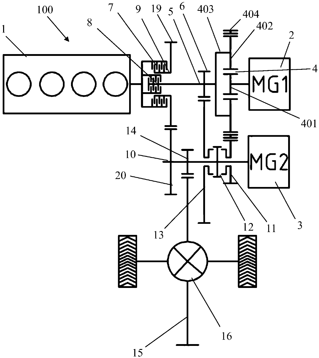
[0040] like figure 1 As shown, the hybrid drive system 100 provided by the first embodiment of the present invention includes an engine 1, a first motor 2, a second motor 3, a single-row planetary gear mechanism 4, a first shaft 5, a driving gear for first gear 6, a first First clutch 7, second clutch 8, second shaft 9, second gear driving gear 19, third shaft 10, outer ring gear driven gear 11, first synchronizer 12, first gear driven gear 13, main minus driving gear 14. 2nd gear driven gear 20 and main minus driven gear 15.

[0041] The single row planetary gear mechanism 4 includes a sun gear 401 , a planet gear 402 , a planet carrier 403 and a ring gear 404 . The planetary gear 402 is externally meshed with the sun gear 401 , and the planetary gear 402 is internally meshed with the ring gear 404 , and the planetary gear 402 is rotatably supported on the planetary gear 403 by a pin shaft arranged on the planet carrier 403 Rack 403.

[0042] The main reduction and driven ...

no. 2 example

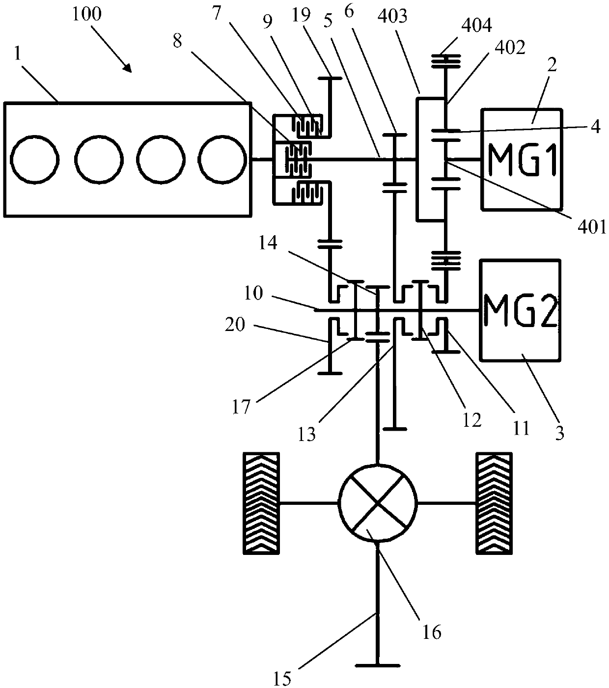
[0050] figure 2 Shown is the hybrid drive system 100 provided by the second embodiment of the present invention, which is different from the first embodiment in that the outer ring gear driven gear 11, the second speed driven gear 20 and the first speed driven gear 13 The idle sleeve is on the third shaft 10 , and the main and reduction drive gear 14 is fixedly connected to the third shaft 10 .

[0051] Another difference from the first embodiment is that the hybrid drive system 100 further includes a second synchronizer 17, and the first synchronizer 12 is arranged on the third shaft 10 and located on the external gear Between the ring driven gear 11 and the first speed driven gear 13, the first synchronizer 12 can selectively engage or disengage with the outer ring gear driven gear 11 and the first speed driven gear 13; The second synchronizer 17 is arranged on the third shaft 10 and is located between the 2nd speed driven gear 20 and the main minus driving gear 14, and th...

no. 3 example

[0054] image 3 Shown is the hybrid drive system 100 provided by the third embodiment of the present invention, which differs from the first embodiment in that the hybrid drive system 100 further includes a third clutch 18, and the first synchronizer 12 is set at On the third shaft 10 and located between the outer ring gear driven gear 11 and the first speed driven gear 13, the first synchronizer 12 can be selectively connected with the outer ring gear driven gear 11 and The first speed driven gear 13 is engaged or disconnected; the third clutch 18 is arranged on the third shaft 10 and is located between the second speed driven gear 20 and the main minus driving gear 14 .

[0055] The outer ring gear driven gear 11, the first synchronizer 12, the first speed driven gear 13, the main minus driving gear 14, the third clutch 18 and the second speed driven gear 20 are aligned along the axis of the third shaft 10. Arranged sequentially in a direction close to the engine 1 .

[00...


PUM


Abstract

The invention belongs to the technical field of hybrid power. The invention relates to a hybrid driving system and a vehicle. The hybrid driving comprises an engine, a first motor, a second motor, a first shaft, a first-gear driving gear, a first clutch, a second clutch, a second shaft, a second-gear driving gear, a third shaft, an outer gear ring driven gear, a first synchronizer, a first-gear driven gear, a main reduction driving gear, a second-gear driven gear, a main reduction driven gear and a single-row planetary gear mechanism. According to the hybrid driving system and the vehicle, themulti-stage speed ratio is adopted, and by controlling the engagement state of the two clutches and the synchronizer, the working modes including motor pure electric driving, engine and motor seriesrange extended driving, engine and motor parallel driving, engine direct driving and the like can be achieved. The engine can work in a section with high fuel economy, so that the fuel economy of thevehicle is improved.

Description

technical field [0001] The invention belongs to the technical field of hybrid power, and in particular relates to a hybrid power driving system and a vehicle. Background technique [0002] Hybrid systems can improve vehicle fuel economy in several ways. For example, the engine can be switched off during idling, deceleration or braking, driving in pure electric drive mode to eliminate efficiency losses due to engine drag. In addition, the energy stored in the power battery generated by regenerative braking or generated by the electric motor during engine operation can be utilized in pure electric drive mode, or supplement the engine's torque or power in hybrid drive mode. [0003] Hybrid vehicles can be driven by combining at least two different power sources. At present, most hybrid vehicles use a gasoline-electric hybrid system, which includes an engine powered by fuel and an electric motor driven by electricity. In order to improve the combustion efficiency of the engine...

Claims


Application Information

Patent Timeline
Patent Type & Authority Applications(China)
IPC IPC(8): B60K6/24B60K6/26B60K6/36B60K6/365B60K6/38
CPCB60K6/24B60K6/26B60K6/36B60K6/365B60K6/38Y02T10/62
Inventor 杨冬生白云辉穆金辉朱新明
Owner BYD CO LTD
Why Eureka
Try Eureka