
Three-dimensional detection device and method based on binocular vision

A three-dimensional detection, binocular vision technology, applied in measuring devices, optical devices, optical testing of defects/defects, etc., can solve the problems of stable imaging, large data processing capacity, low processing efficiency, etc., and achieve strong anti-environmental interference ability , The effect of simple structure configuration and high measurement accuracy

Inactive Publication Date: 2020-04-07
北京伟景智能科技有限公司
View PDF3 Cites 10 Cited by
  • Summary
  • Abstract
  • Description
  • Claims
  • Application Information

AI Technical Summary

Problems solved by technology

However, the current binocular stereo vision cannot reliably and stably extract the 3D information of the target for objects with no texture or very weak texture and blurred boundaries, and the accuracy of analysis and processing is not high. At the same time, in the industrial production and manufacturing process, for some situations that need to penetrate the glass medium for scanning measurement, or when it is necessary to scan the object to be measured on the transparent glass, the object cannot be stably imaged in the sensitive wavelength range of visible light. As a result, it is difficult for the measurement results to accurately reflect the real information of the object to be measured. Due to the transparency of the glass, it is also impossible to use general laser detection methods to perform high-precision smoothness and defect detection on the glass surface.

Method used


Image

  • Three-dimensional detection device and method based on binocular vision
  • Three-dimensional detection device and method based on binocular vision
  • Three-dimensional detection device and method based on binocular vision

Examples


Embodiment Construction

[0025] The technical solution of the present invention will be further described in detail below in conjunction with the accompanying drawings. Apparently, the described embodiments are only a part of the embodiments of the present invention, rather than all the embodiments, and all other embodiments obtained by persons of ordinary skill in the art without making creative efforts belong to the protection scope of the present invention.

[0026] It should be understood that in the description of the present invention, it needs to be explained that the orientation or positional relationship indicated by the terms "upper", "lower", etc. is based on the orientation or positional relationship shown in the drawings, or is the Orientation or positional relationship that is conventionally placed is only for the convenience of describing the present invention and simplifying the description, and does not indicate or imply that the referred device or element must have a specific orientat...


PUM


Abstract

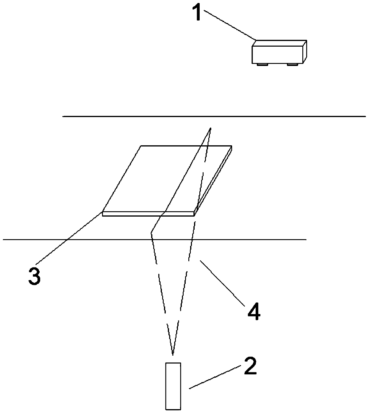
A three-dimensional detection device based on binocular vision comprises a binocular stereo camera, a line laser emitter, a glass panel, an image processor and a central controller, and the line laseremitter controls emission of line laser while the binocular stereo camera is started; the central controller comprises a control module, a matching module and a coordinate calculation module. After an image is preprocessed by the image processor, the central control module matches the corrected image to obtain a laser imaging matching point pair, and the coordinate calculation module calculates to obtain three-dimensional information of an object to be measured according to parallax of left and right views after light penetrates through glass or a transparent object. By utilizing the characteristic that light is transmitted in the transparent object, the transmitted light is received in a binocular multi-angle mode, three-dimensional curved surface three-dimensional information of the transparent object can be accurately and rapidly obtained, the shape, flatness, curvature change and surface quality of the glass panel are rapidly detected, the measurement precision is high, the speedis high, and the cost effectiveness is high.

Description

technical field [0001] The invention relates to the technical field of machine vision, in particular to a three-dimensional detection device and method based on binocular vision. Background technique [0002] The rapid development of robot technology has expanded the application of robots from traditional fixed-target high-precision repetitive operations to flexible operations with variable operating objects and variable operating object positions. Robots urgently need the cooperation of machine vision to obtain three-dimensional information of operating objects. [0003] In deep machine vision, binocular stereo vision based on dual cameras imitates the human binocular working mode and can extract three-dimensional information of objects. However, the current binocular stereo vision cannot reliably and stably extract the 3D information of the target for objects with no texture or very weak texture and blurred boundaries, and the accuracy of analysis and processing is not hig...

Claims


Application Information

Patent Timeline
Patent Type & Authority Applications(China)
IPC IPC(8): G01B11/24G01B11/255G01B11/30G01N21/958G01N21/88G01B11/00
CPCG01B11/002G01B11/24G01B11/255G01B11/30G01N21/8851G01N21/958G01N2021/8887
Inventor 董霄剑曾洪庆张瑞凯
Owner 北京伟景智能科技有限公司
Learn More