
A Measuring Method of Wind Field Gradient

A measurement method and wind field technology, applied in the direction of fluid velocity measurement, velocity/acceleration/impact measurement, measurement device, etc., can solve the action requirements of unmanned aerial vehicles, high accuracy requirements, can not achieve three-dimensional space wind field measurement, Circuit safety, reliability reduction and other issues, to achieve the effect of reducing equipment investment, low cost, simple and lightweight installation

Inactive Publication Date: 2020-10-30
XIAMEN UNIV
View PDF9 Cites 0 Cited by
  • Summary
  • Abstract
  • Description
  • Claims
  • Application Information

AI Technical Summary

Problems solved by technology

This method requires the use of electric energy and cannot work with low energy consumption for a long time; when the long tube is too long, the safety and reliability of the circuit are reduced, and the weight of the entire device is too large
[0007] (4) Use unmanned aerial vehicles to measure wind speed. For example, "a multi-directional wind speed measurement device" disclosed by the invention patent with the authorized announcement number CN103076462B can measure wind speeds in multiple directions at specific points within the wind field range, but cannot Realize the measurement of the three-dimensional space wind field in a specific area
For example, the patent application number CN201610973681.9 discloses "a three-dimensional wind field measurement system suitable for drones and its use method", which discloses a method for wind speed measurement using drones, but this method requires drones. It cannot be used to measure wind speed at high altitude, and requires a large amount of power consumption, cannot be measured for a long time, and has high requirements for the movement and accuracy of drones

Method used


Image

  • A Measuring Method of Wind Field Gradient
  • A Measuring Method of Wind Field Gradient
  • A Measuring Method of Wind Field Gradient

Examples


Embodiment Construction

[0050] The present invention will be described in detail below in conjunction with the accompanying drawings and specific embodiments.

[0051] Such as Figure 1 to Figure 6 as shown,

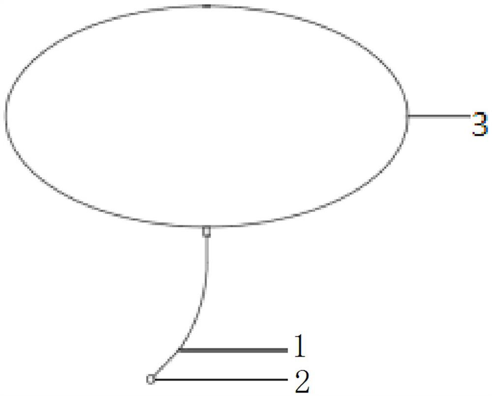
[0052] Whole instrument device is arranged on aerostat 3 such as airship, and the hanging rope 1 of a long about 100 meters of hanging ball at the lower end hangs a hanging ball 2 at the end of hanging rope 1.

[0053] The specific steps for measuring the wind speed by using the hanging rope 1 and the hanging ball 2 are as follows:

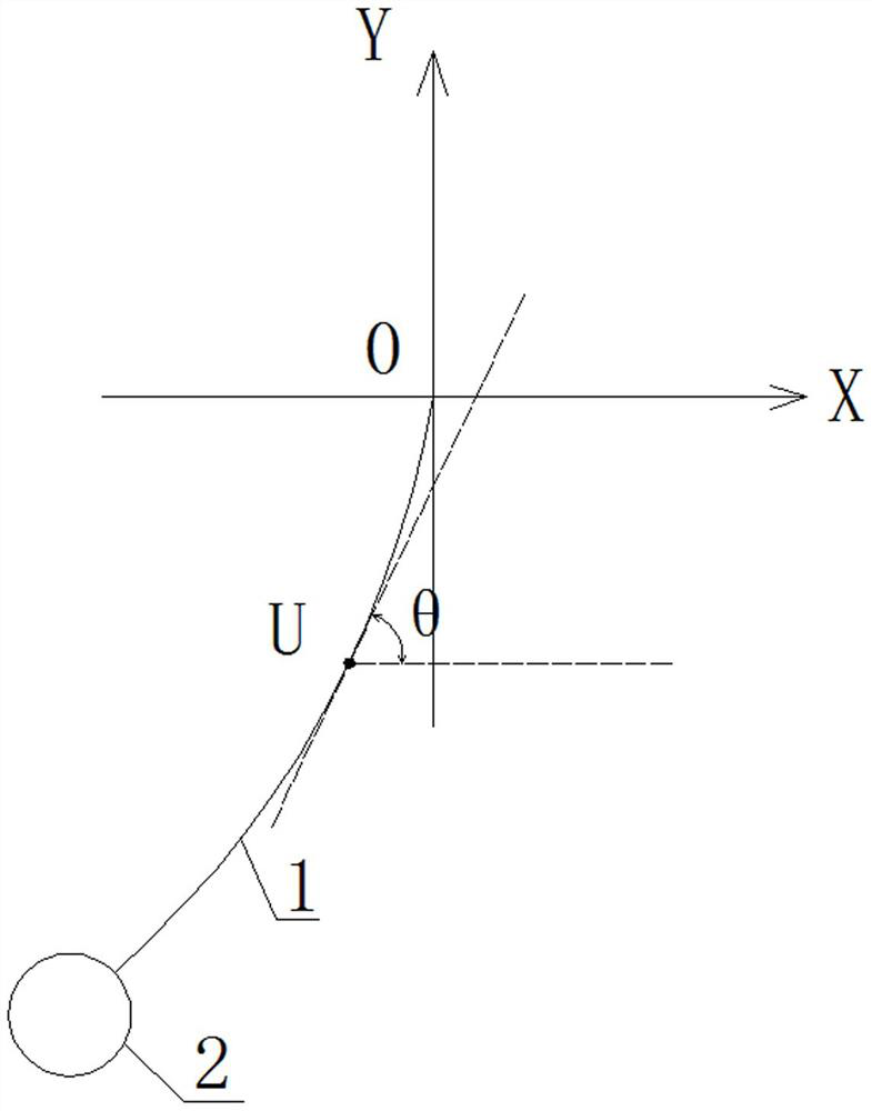
[0054] Step 1: The hanging ball 2 is displaced by the load of the wind field, and at the same time drives the suspension rope 1 to move, and detects the deflection angle of the U point on the suspension rope 1 or the pulling force on the suspension rope 1 through the detector fixed at the lower end of the aerostat 3; There are many ways to measure the deflection angle of the end of the suspension rope 1 involved. The deflection angle of the suspension rope 1 can ...


PUM


Abstract

The invention relates to a wind field gradient measuring method. A lifting rope is suspended at the lower end of an aerostat, and a hanging ball is suspended at the tail end of the lifting rope. The change of the lifting rope along with time is not considered, and the measuring method comprises the following steps: 1, the hanging ball moving under a wind field load; meanwhile, the lifting rope being driven to move, taking any point U on the lifting rope; establishing a rectangular plane coordinate system by taking the fixed end point of the lifting rope as an original point 0, the initial balance position of the lifting rope as a Y axis, the vertical upward direction as a positive direction, the direction vertical to the Y axis as an X axis and the horizontal rightward direction as a positive direction, and detecting an included angle theta between the lifting rope at a U point and an OX axis or a tensile force T1 borne by the lifting rope at the U point. The method does not need a large amount of electric energy consumption, replaces a traditional wind speed detection instrument with a model calculation mode, is high in precision and reliability, can effectively measure the gradient of the high-altitude wind field in a low-energy-consumption, long-term and high-precision mode, and can be used for controlling the airship to stay at a low-wind-speed height and reducing energy consumption.

Description

technical field [0001] The invention relates to a method for measuring wind field gradients, belonging to the technical field of analysis and measurement control. Background technique [0002] The stratospheric airship is a controllable aircraft that is lighter than air. Its main missions are fixed-point flight and long-term windward residence. Since the energy it can carry is limited, reducing energy consumption is to maintain a longer residence time. One of the effective methods of time. One of the ways to reduce energy consumption is to keep the airship at a lower wind speed altitude, which requires real-time measurement of the wind field gradient to control the airship to stay at a lower wind speed altitude. [0003] There are many existing solutions for measuring wind speed, such as: [0004] (1) Wind radar can be used to track sounding balloons to achieve the purpose of measuring wind speed and wind direction, but its measurement time is poor. Due to the time-varying...

Claims


Application Information

Patent Timeline
Patent Type & Authority Patents(China)
IPC IPC(8): G01P5/02
CPCG01P5/02
Inventor 林献武张顾翰
Owner XIAMEN UNIV
Learn More