Air system control method of fuel cell

An air system and fuel cell technology, applied in the field of control, can solve the problems of reducing the output voltage of the fuel cell stack, the fatigue damage of the proton exchange membrane, and the difficulty in realizing accurate control of air flow and air pressure, so as to achieve accurate tracking control and improve response. effect of speed

Active Publication Date: 2020-04-07
BEIJING SINOHYTEC
View PDF9 Cites 21 Cited by
  • Summary
  • Abstract
  • Description
  • Claims
  • Application Information

AI Technical Summary

Problems solved by technology

If the air flow rate is too low, it will cause insufficient oxygen supply to the fuel cell, thereby reducing the output voltage of the fuel cell stack, that is, a "starvation" phenomenon; similarly, if the air flow rate exceeds a certain limit, not only will the output voltage of the fuel cell stack not be increased , but will increase the parasitic power of the air system
Sustained large fluctuations in air pressure will cause fatigue damage to the proton exchange membrane
Therefore, the precise control of air flow and air pressure not only affects the chemical reaction speed of the fuel cell stack and the performance of the proton exchange membrane, but also affects the power generation efficiency and load capacity of the fuel cell stack
[0004] Due to the strong nonlinear and high coupling characteristics of air flow and air pressure, it is difficult for the existing air supply system to precisely control the air flow and air pressure in the fuel cell stack

Method used


Image

  • Air system control method of fuel cell
  • Air system control method of fuel cell
  • Air system control method of fuel cell

Examples


Embodiment Construction

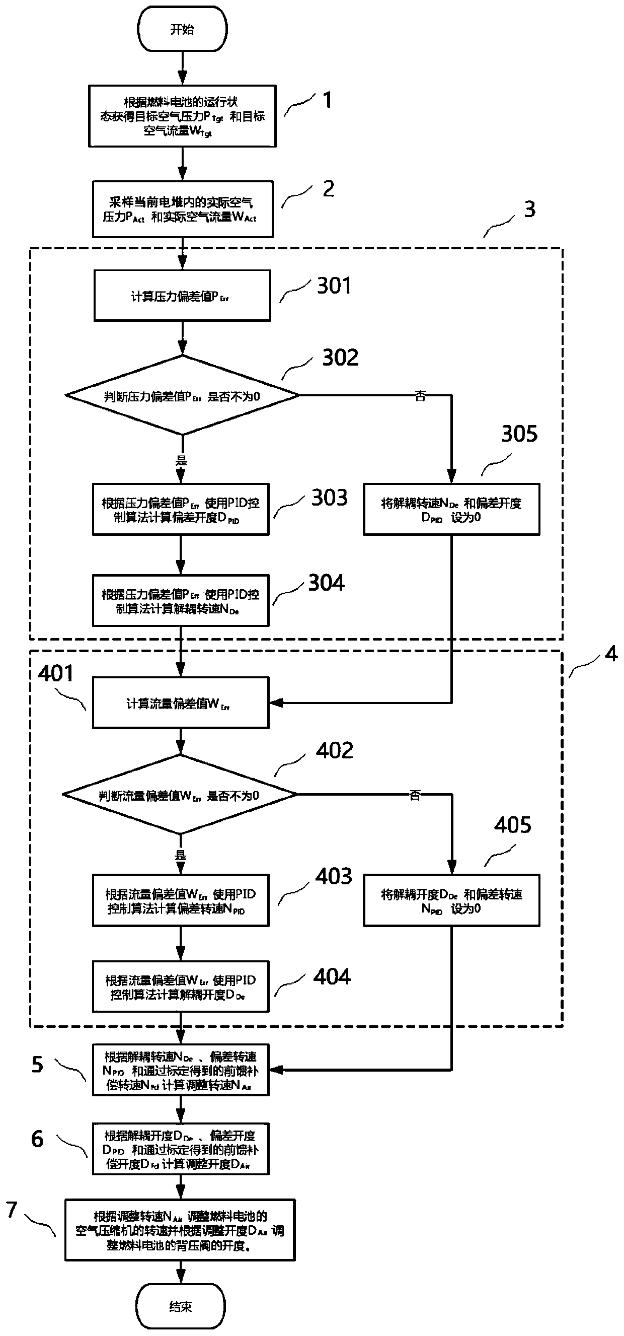
[0046] Figure 1-2 and the following description describe alternative embodiments of the invention to teach those skilled in the art how to make and reproduce the invention. In order to teach the technical solutions of the present invention, some conventional aspects have been simplified or omitted. Those skilled in the art should understand that modifications or substitutions from these embodiments will fall within the protection scope of the present invention. Those skilled in the art will appreciate that the features described below can be combined in various ways to form multiple variations of the invention. As such, the invention is not limited to the alternative embodiments described below, but only by the claims and their equivalents.

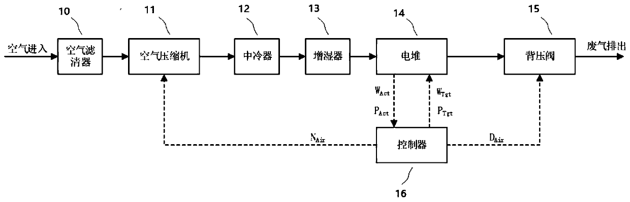
[0047] figure 1 A block diagram of an air system of a fuel cell according to one embodiment of the present invention is shown. Such as figure 1 As shown, the air system includes an air filter 10, an air compressor 111, an intercoole...


PUM


Abstract

The invention provides an air system control method of a fuel cell. The air system control method comprises the steps of obtaining target air pressure and a target air flow according to the operationstate of the fuel cell; sampling the actual air pressure and the actual air flow in a current galvanic pile; calculating a decoupling rotating speed and a deviation opening degree according to the actual air pressure and the target air pressure; calculating the decoupling opening degree and the deviation rotating speed according to the actual air flow and the target air flow; calculating an adjustment rotating speed according to the decoupling rotating speed, the deviation rotating speed and a feed-forward compensation rotating speed obtained through calibration; calculating an adjustment opening degree according to the decoupling opening degree, the deviation opening degree and a feed-forward compensation opening degree obtained through calibration; and adjusting the rotating speed of theair compressor of the fuel cell according to the adjusted rotating speed and adjusting the opening degree of the back pressure valve of the fuel cell according to the adjusted opening degree. The method has the advantages that accurate tracking control over the target values of the air flow and the air pressure is achieved; and the response speed of the air system for the fuel cell is increased.

Description

technical field [0001] The invention relates to a control method, in particular to an air system control method of a fuel cell. Background technique [0002] Hydrogen fuel cell vehicle technology is becoming more and more mature. As a new energy vehicle with zero pollution and zero emissions, hydrogen fuel cell vehicles have increasingly entered the transportation system and have been widely recognized by the public. Fuel cell vehicles use hydrogen as fuel, and through the fuel engine, chemical energy is efficiently converted into electrical energy to drive the vehicle. The whole process only discharges pure water, so it is the most ideal energy-saving, environmentally friendly and zero-emission vehicle to replace traditional fossil fuel vehicles in the near future Transportation. [0003] The air supply system is one of the main systems of the fuel cell, in which air flow and air pressure are two basic parameters of the air supply system, both of which need to be precisely...

Claims


Application Information

Patent Timeline
Patent Type & Authority Applications(China)
IPC IPC(8): H01M8/04298H01M8/0438H01M8/04746
CPCH01M8/04298H01M8/0438H01M8/04746Y02E60/50
Inventor 马腾张国强周鹏飞张禾贾能铀赵兴旺
Owner BEIJING SINOHYTEC
Why Eureka
Try Eureka