
Pay-off device for submarine communication cable laying

A cable laying and pay-off device technology, which is applied to cable laying equipment and other directions, can solve the problems of troublesome pay-off rollers and affect pay-off efficiency, and achieve the effects of improving pay-off efficiency, avoiding friction and improving use effect.

Active Publication Date: 2020-04-07
WEIZHUO PETROTECH (BEIJING) LTD
View PDF9 Cites 2 Cited by
  • Summary
  • Abstract
  • Description
  • Claims
  • Application Information

AI Technical Summary

Problems solved by technology

A pay-off device for sewer communication cable laying in the above-mentioned patent has certain shortcomings: in the process of use, it is very troublesome to replace the new pay-off roller after the cable on the pay-off roller is paid off, which greatly affects the pay-off efficiency, so , it is urgent to design a pay-off device for submarine communication cable laying to solve the above problems

Method used

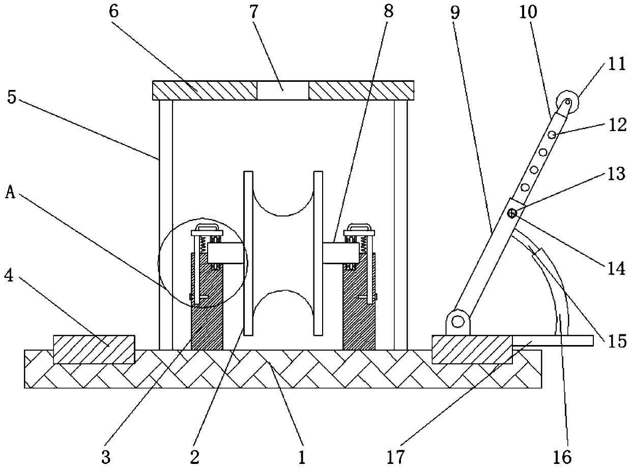

Image

  • Pay-off device for submarine communication cable laying
  • Pay-off device for submarine communication cable laying
  • Pay-off device for submarine communication cable laying

Examples


Embodiment 1

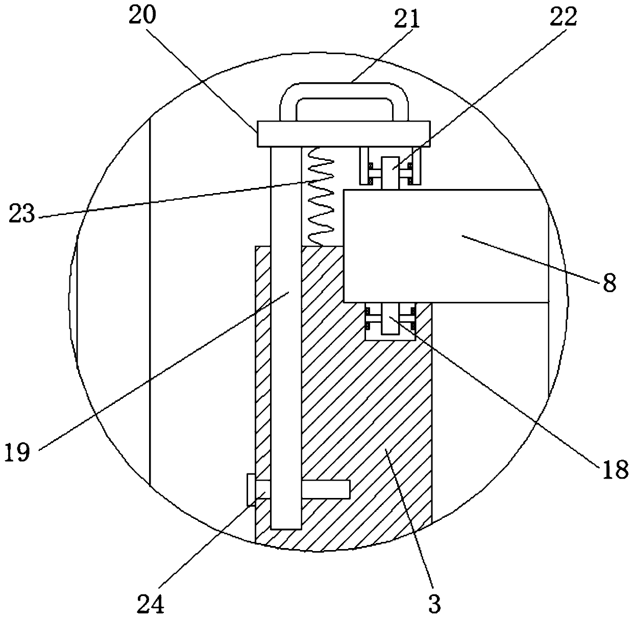
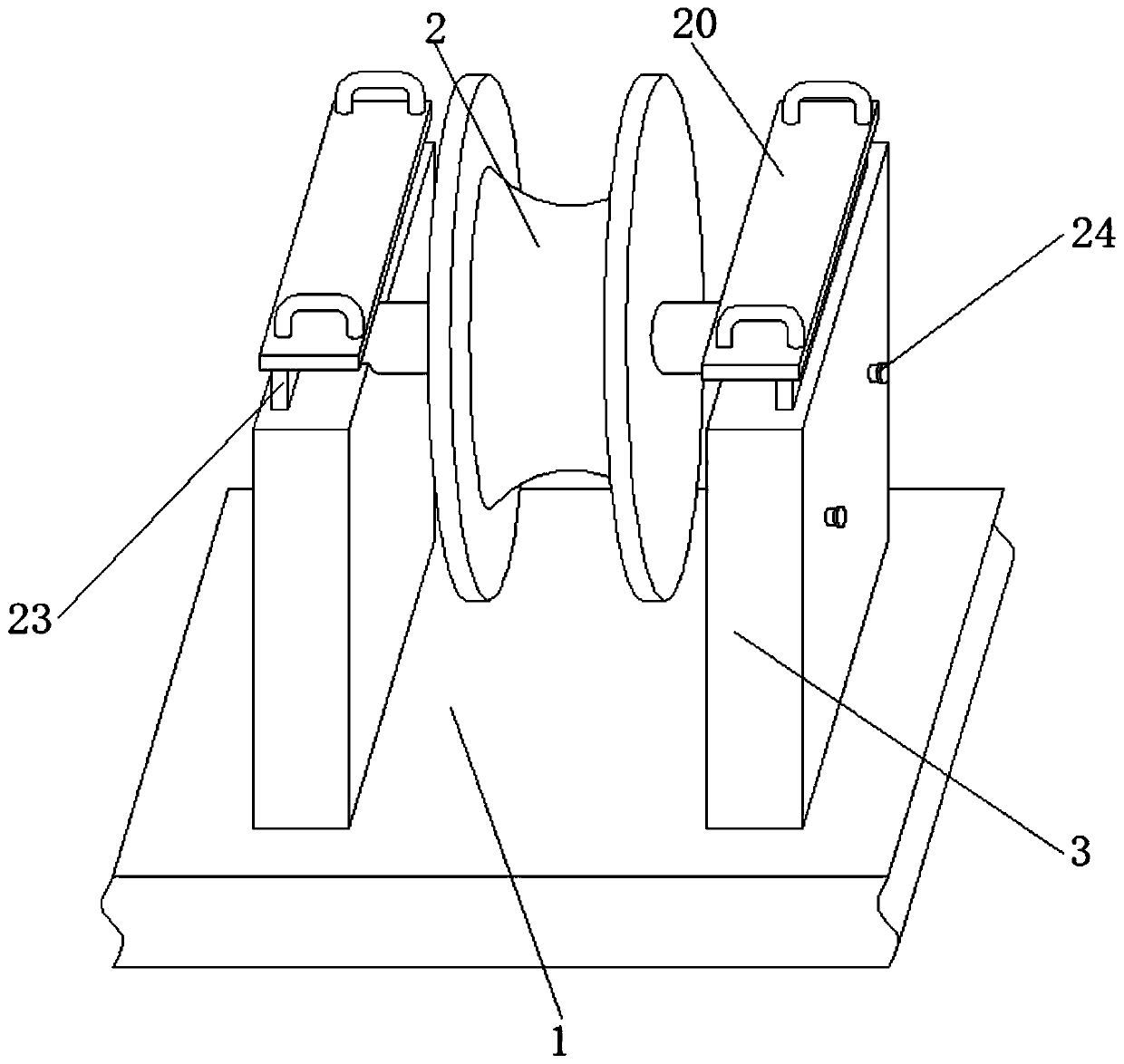
[0029] refer to Figure 1-3 A pay-off device for laying submarine communication cables, comprising a bottom plate 1, four corners of the top outer wall of the bottom plate 1 are welded with uprights 5, and the top outer wall of the upright 5 is welded with a top plate 6, and the top outer wall of the top plate 6 is open There is a wire outlet 7, and the position of the top outer wall of the bottom plate 1 near both sides is welded with a vertical plate 3, and the outer wall of one side of the vertical plate 3 is provided with a card slot, and the inner wall of the card slot is rotatably connected to a rotating shaft 8, and the outer wall of the rotating shaft 8 A pay-off roller 2 is provided, and a fixed groove is provided on the inner wall of the bottom of the slot, and the inner wall of the fixed groove is connected with a lower roller 18 through a pin shaft rotation, and a chute is provided on the top outer wall of the vertical plate 3, and the inner wall of the chute is sli...

Embodiment 2

[0033] refer to Figure 4 , a pay-off device for submarine communication cable laying. Compared with Embodiment 1, this embodiment also includes that the inner wall of the pay-off opening 7 is connected with a wire conduit 25 through bearing rotation, and the shape of the wire conduit 25 is L-shaped, and the wire The inner wall of the pipe 25 is rotatably connected with a side wheel 26 through the ear seat.

[0034] Working principle: when in use, the cable can pass through the conduit 25 when conducting the wire, and the conduit 25 can be rotated at 360 degrees, so that the direction of the device can be flexibly adjusted. At the same time, the side wheel 26 located in the conduit 25 It can assist in setting out wires, avoid friction between the cable and the inner wall of the wire conduit 25, and further improve the use effect of the device.


PUM


Abstract

The invention discloses a pay-off device for submarine communication cable laying. The pay-off device comprises a bottom plate, and vertical rods are arranged at the four corners of the outer wall ofthe top of the bottom plate correspondingly. A top plate is arranged on the outer walls of the tops of the vertical rods, and a pay-off opening is formed in the outer wall of the top of the top plate.Vertical plates are welded to the positions, close to the two sides, of the outer wall of the top of the bottom plate. A clamping groove is formed in the outer wall of one side of each vertical plate, a rotating shaft is rotatably connected to the inner wall of each clamping groove, a pay-off roller is arranged on the outer wall of the rotating shaft, a fixing groove is formed in the inner wall of the bottom of each clamping groove, lower rolling wheels are rotatably connected to the inner wall of the fixing grooves through pin shafts, and a sliding groove is formed in the outer wall of the top of the vertical plate. The inner wall of the sliding groove is slidingly connected with a sliding board. According to the pay-off device, the rotating shaft on the pay-off roller can be rapidly taken down from the vertical plate, so that the pay-off roller is more convenient to replace, the pay-off efficiency of the device is effectively improved, a cable does not rub the underwater position ofthe cable, the protection effect on the cable is achieved, and the use effect is better.

Description

technical field [0001] The invention relates to the technical field of cable laying, in particular to a pay-off device for laying submarine communication cables. Background technique [0002] The through-line cable is a cable for transmitting telephone, telegraph, fax files, TV and radio programs, data and other electrical signals. It is twisted by more than one pair of mutually insulated wires. , High transmission stability, good confidentiality, less affected by natural conditions and external interference, etc. Now, with the accelerated development of cities, communication cables are laid on the seabed in urban construction to solve the problem of limited space above the ground. [0003] After searching, the Chinese Patent Publication No. is CN208369092U, which discloses a pay-off device for sewer communication cable laying, including a base, and the front and rear sides of the left side of the top of the base are fixedly connected with support tubes, and the support A l...

Claims


Application Information

Patent Timeline
Patent Type & Authority Applications(China)
IPC IPC(8): H02G1/10
CPCH02G1/10
Inventor 吴金辉
Owner WEIZHUO PETROTECH (BEIJING) LTD
Learn More